Title: Block Erupter USB mod contest 2015 - 0.3/0.15/0.05 BTC prizes - closed
Post by: TheRealSteve on April 04, 2015, 07:01:24 AM
Wrong forum section? Feel free to move! Block Erupter USB mod contestBTC0.5 total prize money
Ah, the venerable Block Erupter USB - many a miner's first foray into ASIC Bitcoin mining. But what are they doing now? Collecting dust? Fetching $5 each in flash sales only to be found on ebay for $15 each - and selling, too? Still hashing away, forgotten behind a computer tower at a job you were fired from for completely unrelated reasons a long time ago? Or maybe you modded yours. If so, this thread is for you. To celebrate the Block Erupter USB's upcoming 2-year anniversary, I'm 'giving' away BTC0.5 total (a small prize for a small device) in a contest. Post your Block Erupter USB mods here, and I - dictator that I am - shall judge the entries. With any luck you could be a winner (aren't we all, though). Prizes:- 1st place: BTC0.3
- 2nd place: BTC0.15
- 3rd place: BTC0.05
It's not much, but it's more than you're going to get mining with one now, short of being a solo (http://solo.ckpool.org/) Bitcoin (http://bitsolo.net/) mining (http://solomining.com/) lottery (https://solo.nicehash.com/) winner :) Rules:1. Your mod must be a mod of the Block Erupter USB (https://bitcointalk.org/index.php?topic=464496.msg7260096#msg7260096). Let your imagination run wild - be creative. Here's some things that have been done before and aren't going to score very high unless it's exceptional work: - sticking heat sinks onto the chips and calling it a day (http://www.ebay.com/itm/Block-Erupter-Heatsink-Fits-ASICMINER-USB-Bitcoin-Miner-Heatsink-/281186169600)
- overclocking (http://wtfmoogle.com/?p=3334)
- turning it into a (generic) USB-UART adapter (https://bitcointalk.org/index.php?topic=857048)
- turning the heatspreader into jewelry (http://honeybadgerofmoney.com/product/block-erupter-lapel-pin/)
- using it to melt wax (https://www.youtube.com/watch?v=4KphWlLCt64)
- turning it into a door stop / will it blend / RHNB / taofledermaus treatment or general decommissioning/destruction of any kind
2. You must post evidence of the mod in this thread. For some mods that means a picture will be good enough, for the more imaginative mods you might want to make a video and link to it. imgur is a great place for images and videos without sound, youtube is still the go-to place for full video. 3. You must post or PM an address to which potential winnings should be sent (at time of submission or if selected as a winner), and - lest I send BTC into a void - you must sign the following message using that address to prove receivership: Block Erupter USB mod contest 2015 I understand if you haven't already modded your Block Erupter USB - or don't have one to mod - but wouldn't mind a go at grabbing BTC0.3. That's okay, you've got approximately a month to acquire one and/or get modding. - This contest opens effective immediately.
- This contest closes on 2015-05-04 12:00am PST (night of 3rd on 4th). Not sure when that is? Google is ever-so-helpful: current time pst (https://www.google.com/webhp?#q=current%20time%20pst)
Contest address:- Winnings will be paid out from the following address: 1BEUSBxMTLXvZzbYd3gvGckD4dbWiWRJgB (http://btc.blockr.io/address/info/1BEUSBxMTLXvZzbYd3gvGckD4dbWiWRJgB)
- Signature (message as in rule 3): HwvW9w97bUUMTvOL2TZYzb0154eAP95cqwWqDKIaxE2nJvunmOmNkqA9MZF7VDdoaE+RSdK0YsxLp1UaJ0E0KII= (https://brainwallet.github.io/#verify)
Disclaimer / the fine print:I will not give feedback on this thread other than clarification of rules and technical support for posting. This contest is open to any member of the BitcoinTalk Forum. If you're not a member, now's a good time to become one. By participating, you agree to the rules and disclaimer. I'm not allowed to participate. Bummer. friedcat is totes allowed to participate, tho'. Entries past the closing time will be disqualified. I won't be responsible for entries not received due to technical errors. 3 winning entries will be chosen - the number shall be three. Four shalt I not count, neither count I two, except if there's only two entries in which case the remainder of the prize money is distributed by the same weight as the original prizes to those two entrants. Similarly, only one entrant? Winnar! There is no limit to the number of entries allowed per participant, but a single participant only qualifies for a single prize. Results and winners will be announced on 2015-05-04. That's May 4th, not April 5th. My decision is final and no further correspondence will be entertained unless it is entertaining. Prizes are not exchangeable for cash or other products - I mean, by me, you can do whatever you want with it when it's yours. I do not accept responsibility for any tax implications that may arise from the prizes or the use thereof, for you poor sods whose Bitcoin is taxed strictly. This post may receive updates in the below section at any time during the contest period. I told you this was the fine print bit, right?
2015/04/08: Added link to solo.nicehash.com2015/04/13: Added wax melting video2015/04/13.2: Clarified payout address submission2015/04/15: Updated with contests section below
Contests: 1. Block Erupter USB mod contest 2015 - 0.3/0.15/0.05 BTC prizes (https://bitcointalk.org/index.php?topic=1011866)2. Block Erupter USB Three Days of Mining lottery 2015 - 0.1 BTC prize (https://bitcointalk.org/index.php?topic=1028498)3. Block Erupter USB - StickMiners Horizons - 0.1 BTC prize (https://bitcointalk.org/index.php?topic=1043833)
Title: Re: Block Erupter USB mod contest 2015 - 0.3/0.15/0.05 BTC prizes
Post by: S4VV4S on April 04, 2015, 07:10:51 AM
Nice one!
But why is this in Project Development?
Title: Re: Block Erupter USB mod contest 2015 - 0.3/0.15/0.05 BTC prizes
Post by: TheRealSteve on April 04, 2015, 07:21:54 AM
Nice one!
But why is this in Project Development?
Thanks! And that is an excellent question - unfortunately I couldn't pick a good section for it based on section names alone, so I decided to look for previous contests.. and between this section, the gambling section, and marketplace/services, this seemed the most appropriate :) That said, I fully acknowledge there might be a better section - thus the "Wrong forum section? Feel free to move!" in the top right corner :D
Title: Re: Block Erupter USB mod contest 2015 - 0.3/0.15/0.05 BTC prizes
Post by: defcon23 on April 04, 2015, 07:32:51 AM
interesting ! 8) watched! ;)
Title: Re: Block Erupter USB mod contest 2015 - 0.3/0.15/0.05 BTC prizes
Post by: S4VV4S on April 04, 2015, 09:05:42 AM
Nice one!
But why is this in Project Development?
Thanks! And that is an excellent question - unfortunately I couldn't pick a good section for it based on section names alone, so I decided to look for previous contests.. and between this section, the gambling section, and marketplace/services, this seemed the most appropriate :) That said, I fully acknowledge there might be a better section - thus the "Wrong forum section? Feel free to move!" in the top right corner :D I would move it to Bitcoin Discussion if I was you. It would get more views as not that many members are "technical" ;) Once again, Nice One! :D
Title: Re: Block Erupter USB mod contest 2015 - 0.3/0.15/0.05 BTC prizes
Post by: TheRealSteve on April 04, 2015, 12:07:58 PM
I would move it to Bitcoin Discussion if I was you.
It would get more views as not that many members are "technical" ;) Darn those un-technical members! ;) I'll leave it to a mod to relocate if appropriate. It'll get linked from my StickMiners thread later so it'll be found regardless :)
Title: Re: Block Erupter USB mod contest 2015 - 0.3/0.15/0.05 BTC prizes
Post by: achow101 on April 04, 2015, 02:56:34 PM
Awesome contest I'm waiting to see some creative projects!
Title: Re: Block Erupter USB mod contest 2015 - 0.3/0.15/0.05 BTC prizes
Post by: coinableS on April 04, 2015, 04:13:55 PM
But what are they doing now? Collecting dust?
I still have a handful of these, I wouldn't be surprised if they become collectibles in a few years.
Title: Re: Block Erupter USB mod contest 2015 - 0.3/0.15/0.05 BTC prizes
Post by: novak@gekkoscience on April 13, 2015, 04:37:14 PM
Oh wow I just saw this. If I can come up with any more good projects (the USB-UART convertor is mine) I'll have to enter for sure.
--
novak
Title: Re: Block Erupter USB mod contest 2015 - 0.3/0.15/0.05 BTC prizes
Post by: TheRealSteve on April 13, 2015, 05:05:51 PM
Welcoming any and all submissions (that adhere to the rules) :)
There's two other Block Erupter USB(-related) contests coming up, keep an eye on my StickMiners thread for announcements (though I might cross-post across the contest threads anyway). They'll be less involved and thus carry lower prizes (BTC0.1 each) - but if tinkering is not your thing, those should be relatively easy money :)
Title: Re: Block Erupter USB mod contest 2015 - 0.3/0.15/0.05 BTC prizes
Post by: macsheadroom on April 17, 2015, 11:14:35 PM
Title: Re: Block Erupter USB mod contest 2015 - 0.3/0.15/0.05 BTC prizes
Post by: TheRealSteve on April 17, 2015, 11:44:12 PM
Just to note, the contest does mention specifically: Here's some things that have been done before and aren't going to score very high unless it's exceptional work: - sticking heat sinks onto the chips and calling it a day (http://www.ebay.com/itm/Block-Erupter-Heatsink-Fits-ASICMINER-USB-Bitcoin-Miner-Heatsink-/281186169600)
Looks like you also messed with R1 for overclocking? If you're an electronics geek by now, have a look at the LED and how it's being driven. Funky. Long since retired I had dozens of these running 24/7 for a few months, Overclocked with sidehacks kits.
Time to bring it (or possibly another) out of retirement! Details soon :)
Title: Re: Block Erupter USB mod contest 2015 - 0.3/0.15/0.05 BTC prizes
Post by: macsheadroom on April 18, 2015, 01:08:18 AM
Just to note, the contest does mention specifically: Here's some things that have been done before and aren't going to score very high unless it's exceptional work: - sticking heat sinks onto the chips and calling it a day (http://www.ebay.com/itm/Block-Erupter-Heatsink-Fits-ASICMINER-USB-Bitcoin-Miner-Heatsink-/281186169600)
Looks like you also messed with R1 for overclocking? If you're an electronics geek by now, have a look at the LED and how it's being driven. Funky. Long since retired I had dozens of these running 24/7 for a few months, Overclocked with sidehacks kits.
Time to bring it (or possibly another) out of retirement! Details soon :) I'm not expecting to even place but someones gotta get the ball rolling. ;D Bad heat sink placement and amateur soldering skills led to this ones death. Its the only one that died early. I guess I kept him for nostalgia's sake. all the others worked until I sold them on ebay long ago. I over clocked some blades too, those were the days. I remember reading something about that funky LED driver, it got to be over my head. I cant imagine why anyone would mine bitcoins with these anymore, do tell. ;)
Title: Re: Block Erupter USB mod contest 2015 - 0.3/0.15/0.05 BTC prizes
Post by: TheRealSteve on April 18, 2015, 01:26:38 AM
I'm not expecting to even place but someones gotta get the ball rolling. ;D
True that - easy money, too, if yours remains the only entry ;) Bad heat sink placement and amateur soldering skills led to this ones death. That poor thing :( I cant imagine why anyone would mine bitcoins with these anymore, do tell. ;) Three days of mining for a chance at BTC0.1 - mining with a Block Erupter USB hasn't been this profitable since.. ever? Block Erupter USB Three Days of Mining lottery 2015 (https://bitcointalk.org/index.php?topic=1028498)
Title: Re: Block Erupter USB mod contest 2015 - 0.3/0.15/0.05 BTC prizes
Post by: sidehack on April 18, 2015, 08:09:45 PM
I did put out Blade kits, but nothing for the Block Erupter (except sending a handful of parts to one friend). I had at one time seventeen custom-overclocked to 460MH/s but I didn't make any kits for them. I think I still have two, one that works and one that smoked - I also killed the first one while trying to overclock.
I was thinking it might be interesting to rig up a BE with a software-adjustable voltage and clock but I don't think there's enough free pins on the micro. Maybe hardware-adjustable would be good enough.
Title: Re: Block Erupter USB mod contest 2015 - 0.3/0.15/0.05 BTC prizes
Post by: TheRealSteve on April 18, 2015, 08:57:01 PM
Be sure to throw one at the mining lottery - just not the overclocked ones, as it seems you'd be quickly disqualified! ;)
Title: Re: Block Erupter USB mod contest 2015 - 0.3/0.15/0.05 BTC prizes
Post by: sidehack on April 18, 2015, 09:06:36 PM
I might point a BM1384 board at it if I can talk one into running at 6MHz instead of 100+
Title: Re: Block Erupter USB mod contest 2015 - 0.3/0.15/0.05 BTC prizes
Post by: macsheadroom on April 19, 2015, 08:34:32 PM
Looking back I see I got those kits from member rumak and ebay, but I did get my blade kits from sidehack.
Come on guys, are you going let my hack job hack take this win, lets see em'! :P
Title: Re: Block Erupter USB mod contest 2015 - 0.3/0.15/0.05 BTC prizes
Post by: btct22 on April 20, 2015, 06:57:09 AM
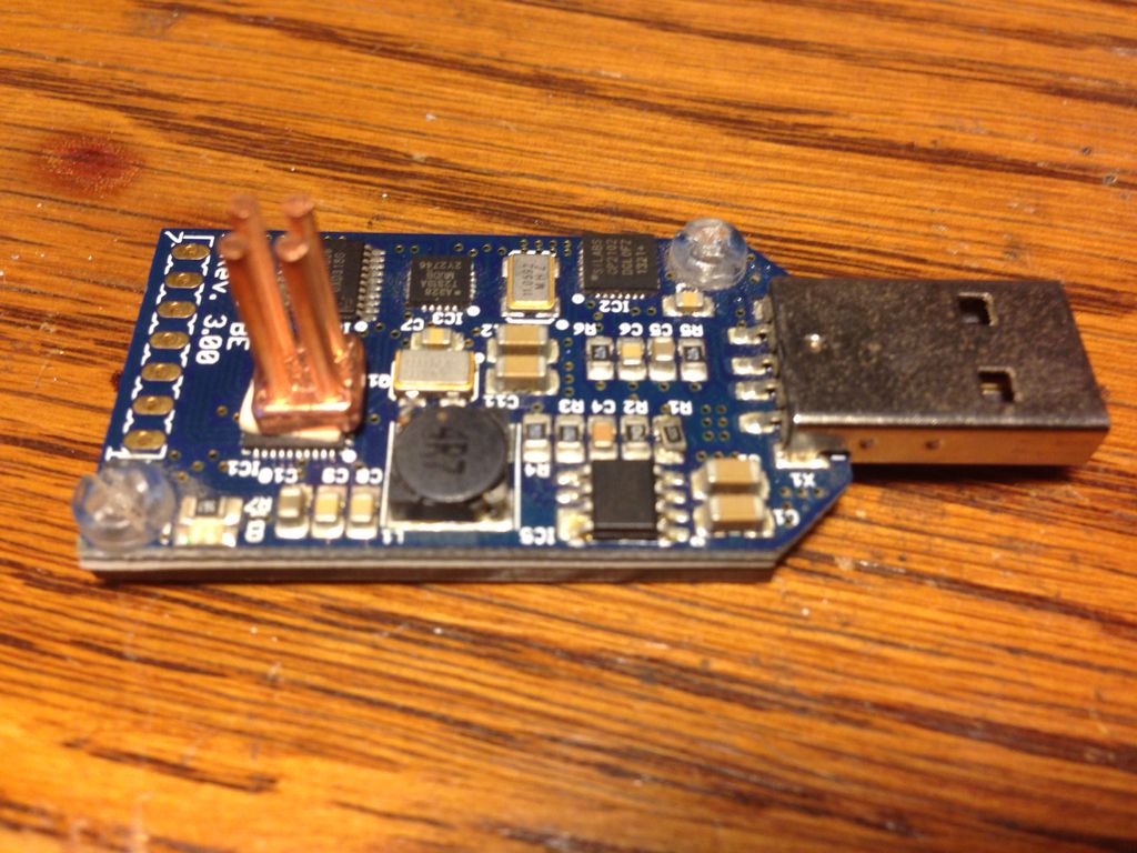
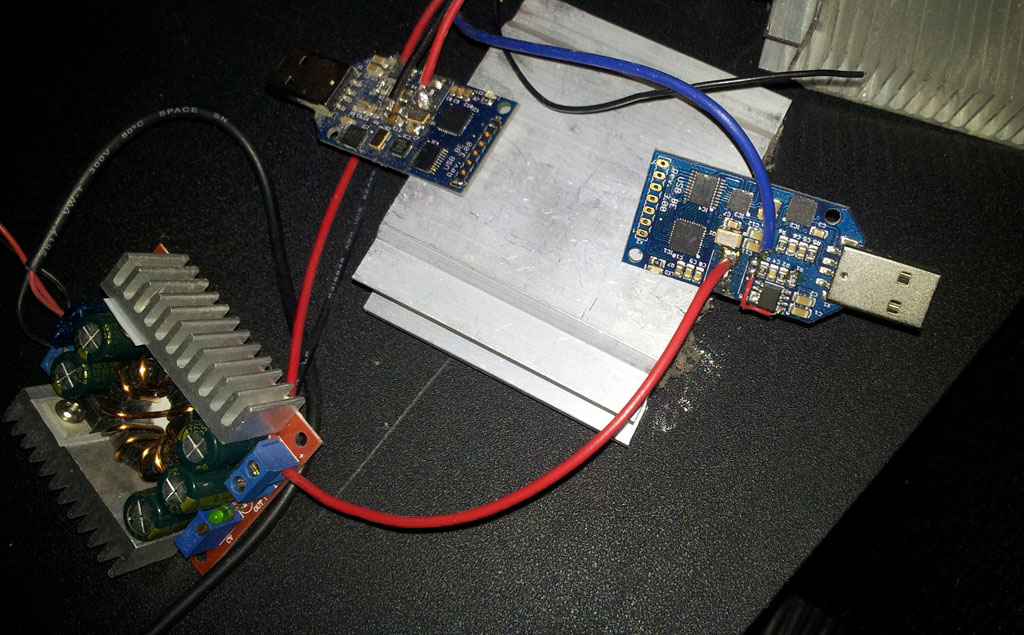
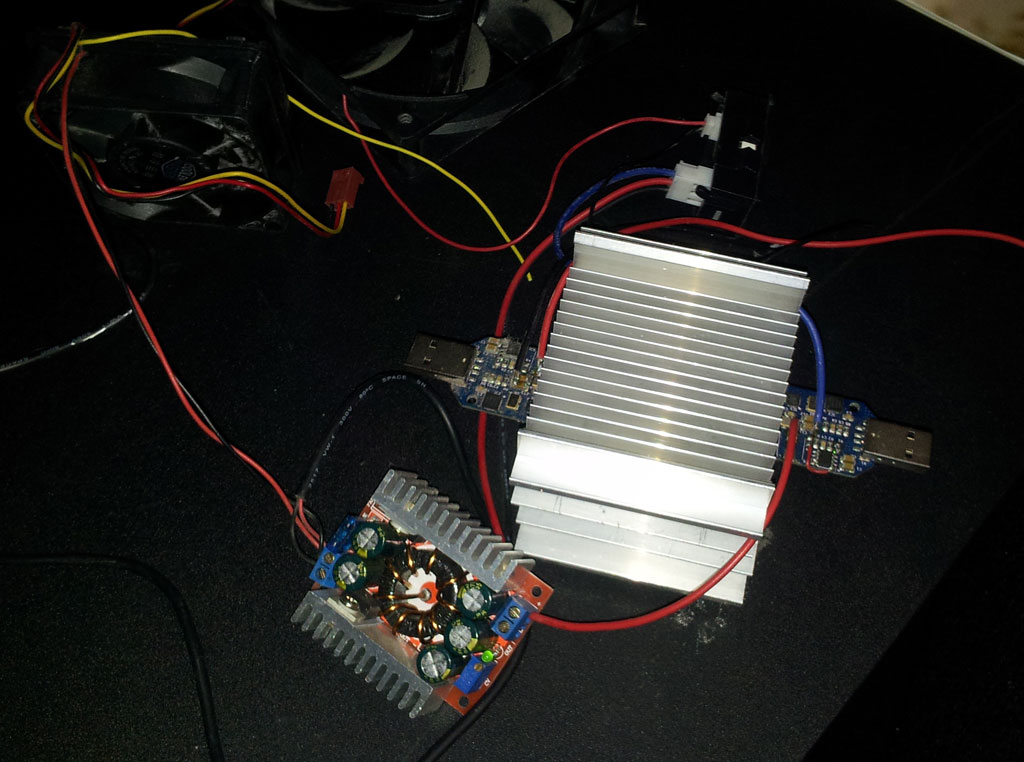
I got quite into modding my BE's - I kept one stock one and all the others got at least a crystal replacement and extra heatsinks. These two I got running at almost double the normal speed, clamped between two finned heatsinks. They had the inductor removed and were directly powered with a variable power supply. This rig was running for months under my desk on top of my PC. http://www.ediy.co.nz/Static/doubleopen.jpghttp://www.ediy.co.nz/Static/doublehs.jpg
Title: Re: Block Erupter USB mod contest 2015 - 0.3/0.15/0.05 BTC prizes
Post by: BitBlitz on April 21, 2015, 02:27:58 AM
OK.. I had about 30 of these things running at one point. Because I preferred to run my Block Erupters with passive cooling, I always removed the heat spreader and epoxied them to proper heat sinks as soon as they arrived. I realized I had an 'ideal heat sink' for the last three I bought. Behold! The 1GH/s coffee warmer with integrated hub... What wasted heat?? https://i.imgur.com/WpbPaYr.jpghttps://i.imgur.com/DGhhT4C.jpg https://i.imgur.com/jfzoUq7.jpgIdeally, one would overclock them or run more than three for the extra heat, but my laptop would only run three stock Block Erupters per USB port before a powered hub was needed. I didn't want to deal with extra cords. These three avoided the early retirement faced by the other Block Erupters when more efficient hardware arrived. https://i.imgur.com/lccONU6.jpg I eventually retired the mug to my office bookshelf, until today. I once left the coffee mug on the kitchen counter (with the cables and hub removed), and the wife ran it through the dishwasher. It survived, and still works today. :D
Title: Re: Block Erupter USB mod contest 2015 - 0.3/0.15/0.05 BTC prizes
Post by: BitBlitz on April 26, 2015, 03:11:51 AM
Where are all the hacks? I want to see the hacks!! I recall seeing pics of Block Erupters cooled in oil, insane cooling solutions, stands made out of wood, metal, Lego, and even cardboard boxes.
Title: Re: Block Erupter USB mod contest 2015 - 0.3/0.15/0.05 BTC prizes
Post by: helipotte on May 01, 2015, 01:17:48 AM
My UARTs for underclocked S1 blades. Turning these off this weekend but was a fun project. 8 of them do 400GH. :) https://i.imgur.com/w5eBxlQ.jpgEven found a use for the 49-port hub!
Title: Re: Block Erupter USB mod contest 2015 - 0.3/0.15/0.05 BTC prizes
Post by: TheRealSteve on May 03, 2015, 06:57:19 PM
Contest 3: Block Erupter USB - StickMiners Horizons - 0.1 BTC prize (https://bitcointalk.org/index.php?topic=1043833)
Is about to go live - good luck :)
Title: Re: Block Erupter USB mod contest 2015 - 0.3/0.15/0.05 BTC prizes
Post by: btct22 on May 04, 2015, 05:27:38 AM
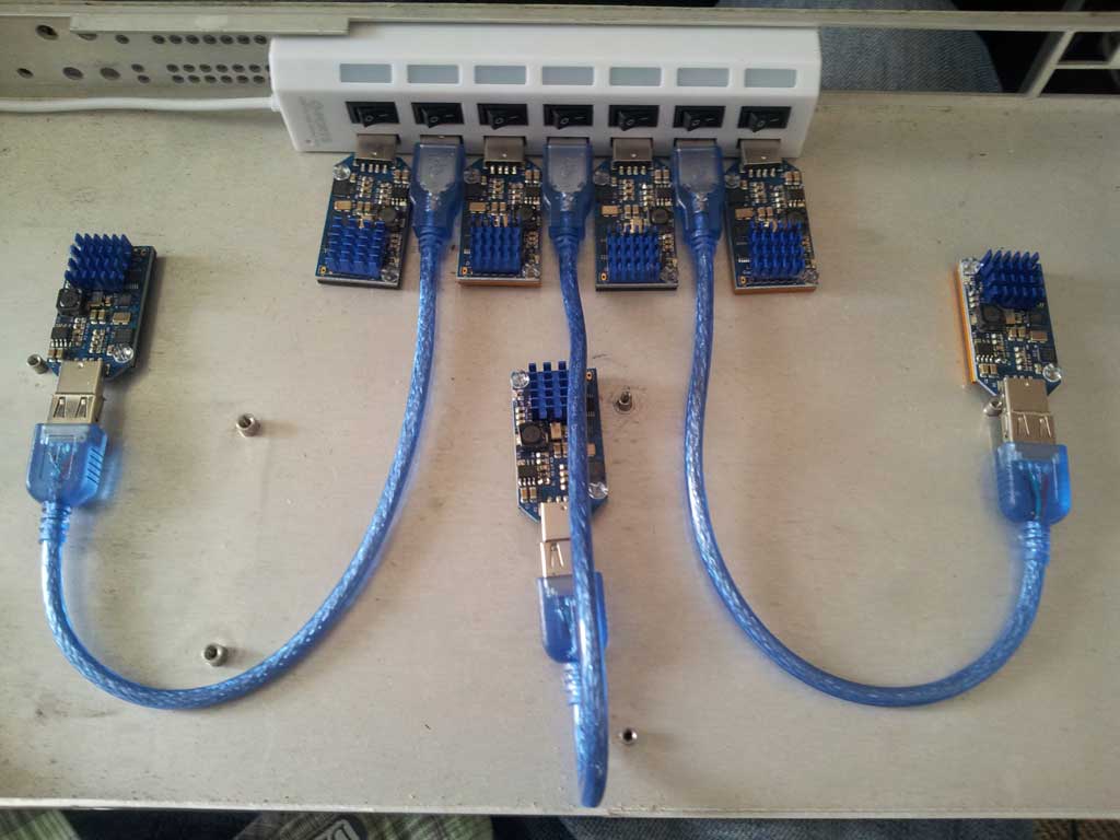
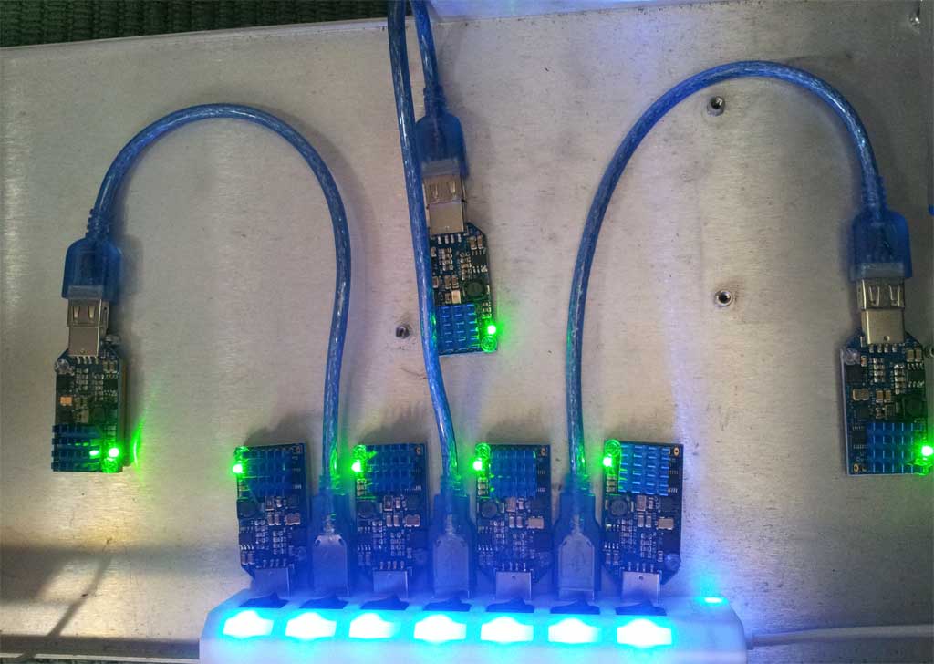
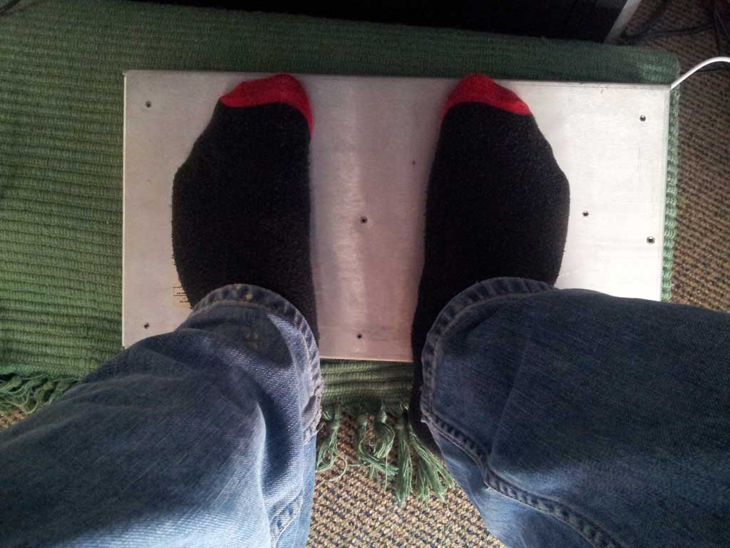
Winter is well on it's way here in New Zealand, so I'm going to use some of my overclocked Erupters (crystal swapped out, all 7 running at ~430Mh/s each) for another useful purpose apart from the odd satoshi here and there - heating my feet! I used an old router case I had lying around + a 7 port hub. Fortunately this hub's port orientation means that each Erupter is perfectly flush with the metal case. If it gets too hot, the hub has individual switches for each port, providing built in temperature selection options. Each Erupter is firmly attached to the metal with double sided heatsink tape. There are 4 of them concentrated around where my toes will be and 3 more for general warmth. I still need to pipe in a couple of amps of external power from my PC's power supply to the hub's power port, but I'm running out of time to get that done, so I thought I'd post a few pictures of the mod now. I'll follow up with an IR temp reading of the metal surface when in use if this entry gets anywhere :) http://www.ediy.co.nz/Static/foot2.jpghttp://www.ediy.co.nz/Static/foot3.jpghttp://www.ediy.co.nz/Static/foot1.jpg
Title: contest closed
Post by: TheRealSteve on May 04, 2015, 07:26:25 AM
It's been 2015-05-04 12am PST - the contest is now officially closed, and the winners will be announced later today :)
Title: Re: Block Erupter USB mod contest 2015 - 0.3/0.15/0.05 BTC prizes
Post by: TheRealSteve on May 04, 2015, 10:53:58 PM
After quick yet careful review, I've decided on the following ranking: - btct22 / footwarmer - wins BTC0.3
- BitBlitz / coffee warmer - wins BTC0.15
- helipotte / block erupters turned USBSER - wins BTC0.05
- btct22 / massive overclock
- macsheadroom / four pillars heatsink
Everybody's winnings will be paid out to the address of their choice (post here or in PM) - please don't forget to sign the message so the transaction doesn't disappear into the void.
I will be posting some of my own mods and related bits and pieces here in the next few days as well :)
Title: Re: Block Erupter USB mod contest 2015 - 0.3/0.15/0.05 BTC prizes
Post by: macsheadroom on May 05, 2015, 06:39:00 PM
That was cool, congrats to the winners. I really liked the ingenuity of these hacks, well done!
Title: Re: Block Erupter USB mod contest 2015 - 0.3/0.15/0.05 BTC prizes
Post by: toldy on May 07, 2015, 05:16:51 PM
What? That's it? I don't understand!!!
Where is the hack that takes a standard block erupter and turns it into an Antminer U2?
Isn't it as simple as adding a large heatsink and clipping pin 3?
Come on people!!!
Title: Re: Block Erupter USB mod contest 2015 - 0.3/0.15/0.05 BTC prizes
Post by: TheRealSteve on May 07, 2015, 06:41:03 PM
Well all you'd need to do is replace the 12MHz oscillator with a 72MHz one - use a trimpot to find a value of R1 that runs it stable*, then flip the equation around to get sane (i.e. readily available) values for R1 and R2, and off you go** ;)
* presumably this involves liquid nitrogen cooling
** for practical silicon reasons, this wouldn't actually work
Hopefully I'll get around to posting my mods before/around this weekend. In the mean time, there'll be a new contest along the lines of the Horizons one to get rid of the excess from the last 3 + a little extra to round it out. Keep an eye on my StickMiners thread for a pointer to that one.
Title: Re: Block Erupter USB mod contest 2015 - 0.3/0.15/0.05 BTC prizes
Post by: TheRealSteve on May 08, 2015, 05:34:42 PM
Just a minor heads-up: in about an hour and a half (noon PST), the last in this series of contests will go live: Block Erupter USB - StickMiners Googly Eyes - 0.1BTC prize (https://bitcointalk.org/index.php?topic=1053725)
Title: Re: Block Erupter USB mod contest 2015 - 0.3/0.15/0.05 BTC prizes - closed
Post by: TheRealSteve on June 13, 2015, 02:24:08 PM
I promised my mods - better (a month) late than never :)
| Black Erupter USB | | | https://i.imgur.com/jxsAF4Pt.jpg (https://i.imgur.com/jxsAF4P.jpg) Black Erupter USB | This is the first 'mod' - an all-black (except for the LED - couldn't source a suitable IR LED, which would have shown it hashing only on camera) Block Erupter USB
| https://i.imgur.com/iSvE15Ct.jpg (https://i.imgur.com/iSvE15C.jpg) Black Erupter USB plugged in | | https://i.imgur.com/QhEk35Vt.jpg (https://i.imgur.com/QhEk35V.jpg) Thermal indicator patches | Putting a bit of color back in there using thermochromic sheet material (range is approximately 25-50°C) - top left is a still, the other 3 show starting up, the back side, and powering down respectively.
| Block Erupter USB heating up (https://youtu.be/ToBNavYnkXk) [youtu.be] | Block Erupter USB cooling down (https://youtu.be/qd__sh4cUBw) [youtu.be] | Ambient temperature was a bit on the high side, but still surprising to see the BE100 and power regulator heat up as quickly as they do without even hashing yet.
| Block Erupter USB heat sink heating up, cooling (https://youtu.be/BFhalzrDp08) [youtu.be] | | Block Erupter USBleep | | | https://i.imgur.com/cPIydEEt.jpg (https://i.imgur.com/cPIydEE.jpg) Perfboard Erupters? | "Familiar shape - but perfboard? Surely he didn't?" - I surely didn't.
I did, however, use a bunch of old component tech to cobble together a pulse detector/stretcher with audiovisual output - matching the Block Erupter USB shape.
Why? Because I can, of course - and because detecting the Block Erupter USB's signal of finding a golden nonce (or error) on hardware is a bit tricky; the LED is activated by pulling a pin on the 74HC574 low, and messing with the circuitry itself made the Block Erupter USB throw HW error after HW error.
A non-invasive light pulse detection circuit is easily made using a single chip, something programmable, or by digging around in boxes of old parts and finding a 4047 (all that's needed to stretch a pulse, itself caught by a photodetector) and a 555 for audio signaling. Add a few pots to adjust sensitivity, pulse duration, pitch and volume, and off you go. The power supply however can be drawn from the Block Erupter USB on the appropriate pads.
Demonstrations with audio (you'll want to lower your volume - 'Here Be Beepdragons'):
Pulse stretcher (optical, audible, and TTL out), calibration and preference (http://youtu.be/c9ujQUUEhks) [youtu.be]
Block Erupter USB mining away with pulse stretched slaved (http://youtu.be/4dCP69CX8PM) [youtu.be]
( While this is pretty silly - though amusing if applied to dozens of Block Erupter USBs, perhaps - the output pulse is also fed out through one of the header pins, making it suitable for use as e.g. a flash slave trigger, lightning detector, non-invasive power meter monitoring, etc. )
| https://i.imgur.com/hAG4n43t.jpg (https://i.imgur.com/hAG4n43.jpg) Pulse detector/stretcher | | Block Erupter full teardown | | | https://i.imgur.com/bsoPJy8t.jpg (https://i.imgur.com/bsoPJy8.jpg) Block Erupter USB bottom with soldermask | But how do you know which of those pads to use?
Well, other people have already done some of the work in figuring out those pads when they worked on overclocking - a simple multimeter will do for figuring out voltages and continuity. http://wtfmoogle.com/?p=3334 (http://wtfmoogle.com/?p=3334)
Some have taken a quick look at parts. http://codinginmysleep.com/asicminer-block-erupter-teardown/ (http://codinginmysleep.com/asicminer-block-erupter-teardown/)
Others already attempted to figure out the Block Erupter USB schematic - but abandoned their efforts. http://openschemes.com/2013/09/15/reversing-the-usb-block-erupter-part-1/ (http://openschemes.com/2013/09/15/reversing-the-usb-block-erupter-part-1/)
Turns out, if anybody's ever done a teardown of one, I can't find it. That's okay, I don't mind hypothetically duplicating effort.
On the left and right a sight that should be somewhat familiar - the bottom of a Block Erupter USB, showing zero components but a bunch of solder mask that's inhibiting thermal transfer to the heat sink and so was sometimes removed by those overclocking (https://bitcointalk.org/index.php?topic=241652.msg2766343#msg2766343), resulting in more or less the image on the right.
| https://i.imgur.com/OPJrIw6t.jpg (https://i.imgur.com/OPJrIw6.jpg) Block Erupter USB bottom without soldermask | | https://i.imgur.com/VjFcYrFt.jpg (https://i.imgur.com/VjFcYrF.jpg) Block Erupter USB top without components | But what's the top look like under all those components?
Like a world of fluxy hurt, at first, shown on the left.
But on the right, after clean-up and sanding, it looks like a fairly neat board.
There's just one problem with this board - and no, it's not that it - it's that those vias on the top go to the bottom but don't appear to go anywhere else.
(https://bitcointalk.org/index.php?topic=241652.msg2575054#msg2575054">isn't an Metal Core PCB / aluminum substrate[/url) | https://i.imgur.com/N1IWAQ2t.jpg (https://i.imgur.com/N1IWAQ2.jpg) Block Erupter USB top without soldermask | | https://i.imgur.com/r7yxnBLt.jpg (https://i.imgur.com/r7yxnBL.jpg) Shining a light through a Block Erupter USB | Shining a light on it - quite literally - makes it clear that we're dealing with a multi-layer PCB.
| | | https://i.imgur.com/OxW6WR8t.jpg (https://i.imgur.com/OxW6WR8.jpg) Block Erupter USB layer 2 | Specifically, it's a 4-layer PCB - which is a bit surprising, as 4-layer PCBs are a fair bit more expensive than 2-layer ones. It does make it easier to route, however, and can also help with power distribution and keeping clean signals.
After not-so-careful further sanding (destroyed a few traces - that's okay, took plenty of pictures inbetween), on the left is layer 2 (as seen from the top), and on the right is layer 3 (as seen from the bottom).
And with that, redrawing the PCB becomes a breeze. But first, the schematic. And for that, I need to start with a <u>BOM</u>
| https://i.imgur.com/e2335pXt.jpg (https://i.imgur.com/e2335pX.jpg) Block Erupter USB layer 3 | | http://www.wakuangji.cn/wp-content/uploads/2013/08/USB-miner-bom-300x151.jpg (http://www.wakuangji.cn/wp-content/uploads/2013/08/USB-miner-bom-300x151.jpg) Block Erupter USB informal BOM courtesy of wakuangji.cn | Now, the BOM for a Block Erupter USB is actually available (http://www.wakuangji.cn/asic/usb-miner-bom/) - albeit with a bit of Chinese, missing values and a few outdated package sizes, as shown on the left.
But I did go through the trouble of de-soldering all those components (which is to say I put the board on a hot plate and just picked them off as the tin melted), so why not go for a more visual BOM? Why not indeed, and presented on the right.
( Values measured using handy-dandy M328 type 'Transistor Tester' (https://www.google.com/webhp?#q=m328%20transistor%20tester) )
The part selection was done at Digikey, and you can grab a cart of all the components minus the BE100 right here: digikey.com/short/7nd4rq (http://www.digikey.com/short/7nd4rq). Yes, the total is $13.92 - much higher than what most would pay for a completely assembled Block Erupter USB at this point. ASICMiner was able to buy in bulk through more direct suppliers - if you order multiples of these components you will find Digikey gives a bit of a discount as well; the list 'as is' will already suggest you get 10 of the small capacitors instead of 6 to get a better total price.
For a flat list of the BOM:
1 x 931K-ND / CONN PLUG USB A-TYPE SMD / USB A connector / X1
1 x SRR7032-4R7MCT-ND / FIXED IND 4.7UH 2A 42 MOHM SMD / 4.7uH inductor / L1
1 x 300-8244-1-ND / OSC XO 12.000MHZ HCMOS TTL SMD / 12MHz tri-state oscillator / Q1
1 x 535-11280-1-ND / CRYSTAL 11.0592MHZ 18PF SMD / 11.0592MHz crystal / Q2
1 x 785-1155-1-ND / IC REG BUCK SYNC ADJ 3A 8SOIC / AOZ 1021 3A buck regulator / IC5</br >
1 x MM74HC574MTCXCT-ND / IC D-TYPE POS TRG SNGL 20TSSOP / Octal D-type flip-flop / IC4
1 x ATTINY2313A-MU-ND / IC MCU 8BIT 2KB FLASH 20QFN / Atmel ATtiny 2313A / IC3
1 x 336-1160-1-ND / IC USB-TO-UART BRIDGE 28VQFN / Silicon Labs CP2102 USB-UART bridge / IC2
4 x 587-1356-1-ND / CAP CER 22UF 10V Y5V 1206 / 22uF ceramic capacitor / C1,C2,C11,C12
2 x 311-1462-1-ND / CAP CER 10UF 6.3V Y5V 0805 / 10uF ceramic capacitor / C5,C10
6 x 1276-1007-1-ND / CAP CER 0.1UF 50V Y5V 0805 / 100nF ceramic capacitor / C3,C4,C6,C7,C8,C9
2 x P7.50KCCT-ND / RES SMD 7.5K OHM 1% 1/8W 0805 / 7.5kOhm resistor / R3,R4
2 x P4.70KCCT-ND / RES SMD 4.7K OHM 1% 1/8W 0805 / 4.7kOhm resistor / R5,R6
1 x P2.40KCCT-ND / RES SMD 2.4K OHM 1% 1/8W 0805 / 2.4kOhm resistor / R2
1 x P750CCT-ND / RES SMD 750 OHM 1% 1/8W 0805 / 750 Ohm resistor / R1
1 x P560CCT-ND / RES SMD 560 OHM 1% 1/8W 0805 / 560 Ohm resistor / R7
1 x 754-1939-1-ND / LED 2.0X1.2MM GREEN SMD / LED, green, Vf ~= 2.6V / LED
1 x na / na / ASICMiner BE100 / IC1
ATTENTION: Ordering the ATtiny won't do you much good without also having the firmware that goes onto it - which, as far as I know, was not released, and dumping is probited by the set lock bits. So if you wanted to build a Block Erupter USB yourself, you would first need to source a Block Erupter USB to get that chip, even if you manage to salvage BE100 chips off of e.g. a Block Erupter Cube.
| https://i.imgur.com/KOvhldTt.jpg (https://i.imgur.com/KOvhldT.jpg) Block Erupter USB visual BOM | | https://i.imgur.com/vn74M6Gt.jpg (https://i.imgur.com/vn74M6G.jpg) Innards of a crystal (minus tuning fork) | If you're new to electronics, you might have looked at that BOM and thought "Okay, how do you figure that 12MHz component is an 'oscillator' while the other one a 'crystal'? They look much the same to me."
Right you are - on the outside, they are very similar (and for cheap ones, there's no package difference at all). But on the inside, they're quite different.
Note: Chronology in this post is going out the window for a bit - these parts are salvaged from a later mod which died.
On the left are the innards of the 11.0592MHz crystal, minus the tuning fork. The tuning fork is just a bit of crystal that's cut to an exact size and shape to resonate at the desired frequency. This value has to do with serial communication rates, by the way: 11.0592 divides nicely down to 115k2 baud (http://en.wikipedia.org/wiki/Crystal_oscillator_frequencies), which you may recognize as the standard communication baud rate when mining with a Block Erupter USB.
On the right are the innards of the 12MHz oscillator, minus the tuning fork. While the packages are very similar, you can see there's an extra bit of circuitry in there. That circuitry keeps the crystal oscillating, whereas a crystal typically requires two external capacitors or a pulse 'pinging' it and can vary a slight bit based on electrical and ambient conditions. Suffice it to say that the oscillator tends to be more stable.
While we're tearing things down anyway, let's have a closer look at these components.
| https://i.imgur.com/fnBBueVt.jpg (https://i.imgur.com/fnBBueV.jpg) Innards of an oscillator (minus tuning fork) | | https://i.imgur.com/8YjnakIt.jpg (https://i.imgur.com/8YjnakI.jpg) Oscillator silicon | On the left that tiny, tiny little bit of silicon that's inside the oscillator. Untouched by packaging, these come out nice and pristine.
On the right, an even closer look at that bit of silicon.
| https://i.imgur.com/5VSSwfot.jpg (https://i.imgur.com/5VSSwfo.jpg) Oscillator silicon close-up | | https://i.imgur.com/kl3ZOL8t.jpg (https://i.imgur.com/kl3ZOL8.jpg) Chips shaved down to bond wires | For the other chips, the ideal method would be to dissolve the package with some fuming nitric acid - but that's some really nasty stuff, and the next closest thing works only when heated and will then happily start dissolving the silicon as well.
So instead, they're just sanded down, roughly at first until the bond wires (the tiny little gold wires that connect the silicon to the package pins) become visible - as shown on the left - and then continued using a finer grit until either the package material breaks away from the silicon or the silicon gets ruined.
| | | https://i.imgur.com/uicAcs5t.jpg (https://i.imgur.com/uicAcs5.jpg) LED (off) | Completely forgot about the LED. Using the one from the Black Erupter USB here instead. Left is unlit, right is lit (I know, obvious.)
| https://i.imgur.com/8C2YFLkt.jpg (https://i.imgur.com/8C2YFLk.jpg) LED (on) | | https://i.imgur.com/GuapMWzt.jpg (https://i.imgur.com/GuapMWz.jpg) AOZ1021 silicon | First up, the AOZ1021 buck regulator - and a piece of lint - showing the 3 distinct silicon chips inside the package.
Sanded further down past the silicon, the underlying geometry becomes visible.
| https://i.imgur.com/x8OdgFbt.jpg (https://i.imgur.com/x8OdgFb.jpg) AOZ1021 carrier | | https://i.imgur.com/q0WOYdSt.jpg (https://i.imgur.com/q0WOYdS.jpg) 74HC574 silicon | Next, the 74HC574 octal D-type flip flop (NXP). The package image on the right shows just exactly how tiny that little chip actually is. Now you know why companies are trying to get away from relatively large packages like these.. it's a lot of wasted space.
| https://i.imgur.com/ZSyv0t9t.jpg (https://i.imgur.com/ZSyv0t9.jpg) 74HC574 carrier | | https://i.imgur.com/n2Rfnj1t.jpg (https://i.imgur.com/n2Rfnj1.jpg) CP2102 silicon | The Silicon Labs CP2102 USB-UART bridge. Very pretty! The packaging on this chip broke away somewhat cleanly, which makes me think there may have been a slight cavity (not uncommon, sometimes by design) above the silion.
These packages aren't as pretty when sanded down to the pins, as it's just one rectangle in the middle of the chip on a metal carrier that tends to extend to the corners, and the pins on the edges. So instead, have a close-up of the reddish array of the image on the left. At the top is some of the logic bits and you can see that this is a much, much smaller node than that used in the oscillator.
| https://i.imgur.com/btqwEYbt.jpg (https://i.imgur.com/btqwEYb.jpg) CP2102 silicon close-up | | https://i.imgur.com/cfSWDcSt.jpg (https://i.imgur.com/cfSWDcS.jpg) ATtiny2313 silicon (partial) | The Atmel ATtiny2313. Very pretty, but the packaging on this chip was being a right pain in the behind, as evidenced by bits of the packaging stubbornly holding on to the silicon. Further sanding scratched up the silicon, so let me show you that metal carrier for this one on the right.
| https://i.imgur.com/oVMAhVh.jpg (https://i.imgur.com/oVMAhVh.jpg) ATtiny2313 carrier | | https://i.imgur.com/gvQ1wP5t.jpg (https://i.imgur.com/gvQ1wP5.jpg) ASICMiner BE100 close to silicon | Finally, the ASICMiner BE100. On the left, inspection after sanding down a good bit further. Patterns of the silicon underneath the packaging material can start to be seen.
On the right, after a bit more sanding, bits of the packaging material started to chip away. Rather than sanding further, I proceeded with a plastic tool to try and pry away the bits of packaging while damaging the silicon as little as possible.
| https://i.imgur.com/XDVoKZpt.jpg (https://i.imgur.com/XDVoKZp.jpg) ASICMiner BE100 corner of silicon exposed | | https://i.imgur.com/in7rZaHt.jpg (https://i.imgur.com/in7rZaH.jpg) ASICMiner BE100 silicon | In the shot on the left, you can somewhat recognize the hash engine layout pattern you may have seen from other chips.
The details of a Bitcoin Mining ASIC are rather boring, being a repeat of the same structure over and over and over, unless it has a somewhat unique distribution (a la BitFury's first two chips), the only thing that tends to stand out is the <abrr title="Phase-locked loop">PLL[/abbr] - which I can only presume is what the little corner piece is.
I could find no identifying markings like those found on the Butterfly Labs (https://en.bitcoin.it/wiki/File:Asic-butterfly_labs-bitforce_sc-die_detail.jpg), KnCMiner (https://en.bitcoin.it/wiki/File:Asic-kncminer-jupiter-die_detail.jpg), BitFury (http://zeptobars.ru/en/read/bitfury-bitcoin-mining-chip) and other chips.
The people at zeptobars.ru (http://zeptobars.ru/) could surely do a better job - and it's unfortunate that they have not done further decaps of Bitcoin mining chips beyond the first BitFury (BF756C55) and the first Avalon (A3256).
| https://i.imgur.com/4UblQJTt.jpg (https://i.imgur.com/4UblQJT.jpg) ASICMiner BE100 silicon (PLL) | | Block Erupter USB heatsinking | | | https://i.imgur.com/T5NNkMUt.jpg (https://i.imgur.com/T5NNkMU.jpg) Left over parts and new bolts | Slight detour. As I'm now left with a spare heat spreader, silpad and crudely decapped chip eye candy, let's put those to good use.
The spare heat spreader was black, and I actually like that a bit better than one of the reds I have, so that was the first thing to swap.
The next bit is to get the red heat spreader back onto the same Block Erupter USB - but on the other side. This means flipping it over, beveling the edges with a file, and using some longer screws so that they can just pass through one and end up in the other.
Important note: You can't just use screws/bolts 'as is' to do this, as both heatspreaders are threaded, making it physically impossible to tighten one to the other - the screws have to turn free at the heatspreader near the head. While you can buy specialized screws and bolts for this, sticking the screw in a dremel and then running it against the edge of a file will do in a jiffy, as shown on the bottom screw.
A small chip heat sink - of the same type you'll see people sell on e-bay for cooling Block Erupter USBs, usually with a heat sink for every chip, even though the thermal pictures show that it's just the BE100 and the AOZ1021 that get particularly warm out the top - filed down a little bit makes for a perfect fit between the chip and the two heatspreaders without crushing the inductor.
There's bits of plastic between the heads of the screws and the heatspreader - these are basic ring shapes with a cut to the center so that the screws won't scratch up the heatspreader, while you can tug the spacers out quite readily leaving a clean finish.
The relatively small amount of heat generated out the top of the BE100 can now dissipate more readily and the components are a bit more shielded by the other heatspreader. It's a bit bare, though, and tossing that decapped BE100 is a bit of a waste...
| https://i.imgur.com/nh4Zr1nt.jpg (https://i.imgur.com/nh4Zr1n.jpg) Double-decker Block Erupter USB | | https://i.imgur.com/rFUQlZ9t.jpg (https://i.imgur.com/rFUQlZ9.jpg) ASICMiner BE100 shield | With the left over decapped BE100 mounted, slight drop of polyurethane on top to keep it from scratching up any further than I already did, and it's not quite as bare looking.
| https://i.imgur.com/fEsP8tYt.jpg (https://i.imgur.com/fEsP8tY.jpg) ASICMiner BE100 shield | | Block Erupter USB original layout | | | https://i.imgur.com/tMtrrPLt.jpg (https://i.imgur.com/tMtrrPL.jpg) Block Erupter USB with components | Alright, shiny, but back on track. I know what the PCB looks like, I know what the components are and where they go - in case you forgot what a Block Erupter USB looks like, to the left your eyes go - so I can get started on drafting it up.
| | | https://i.imgur.com/wsqfM9ct.png (https://i.imgur.com/wsqfM9c.png) Typical schematic symbol | While it's tempting to go with existing libraries for components - and you probably should use those eventually - when trying to figure things out from a board it's not very helpful when a schematic symbol looks nothing like the part; on the left, an existing symbol for the CP2102 (USB-UART).
On the right, a version that matches the physical layout of the pins. Much easier to work with as there's no mental exercise in figuring out which pin was where on the package, etc.
Of course you do still need to know what pin is what on the components - and while the passives and LED are easy enough, for the chips you'll have to go to the datasheets:
- Oscillator: http://www.abracon.com/Oscillators/ASFL1.pdf (http://www.abracon.com/Oscillators/ASFL1.pdf)
- AOZ1021: http://aosmd.com/res/data_sheets/AOZ1021AI.pdf (http://aosmd.com/res/data_sheets/AOZ1021AI.pdf)
- 74HC547: https://www.fairchildsemi.com/datasheets/MM/MM74HC574.pdf (https://www.fairchildsemi.com/datasheets/MM/MM74HC574.pdf)
- ATtiny2313A: http://www.atmel.com/Images/8246s.pdf (http://www.atmel.com/Images/8246s.pdf)
- CP2102: http://www.silabs.com/Support%20Documents/TechnicalDocs/CP2102-9.pdf (http://www.silabs.com/Support%20Documents/TechnicalDocs/CP2102-9.pdf)
There's no official datasheet for ASICMiner's BE100 that I could find, but I can infer some of the functions as I draw the schematic.
| https://i.imgur.com/Kuvl6awt.png (https://i.imgur.com/Kuvl6aw.png) Physical schematic symbol | | https://i.imgur.com/Lu37r7gt.png (https://i.imgur.com/Lu37r7g.png) Block Erupter USB base schematic layout | Once each component is drawn (both symbol and package), sticking with the physical layout tends to be easiest again - placing each roughly where they are on the board and within the function each fulfills, as shown on the left.
After that, the tedious task of following each trace on the board from one pin to another (and another and another, through a via to yet another) begins, but eventually you end up with something like the schematic on the right.
Throwback: And that's how you know which pad does what - for the Block Erupter USBleep, that's just the 5V source off of the USB port and GND (ground).
It's also how pins on the BE100 can be inferred; they connect to known pins on other components. There will be pins that remain unknowns without further information (that missing firmware on the ATtiny, for example), but in the end it doesn't matter much.
| https://i.imgur.com/IRV1eINt.png (https://i.imgur.com/IRV1eIN.png) Block Erupter USB base schematic wired | | https://i.imgur.com/oQ5Pmqqt.png (https://i.imgur.com/oQ5Pmqq.png) Block Erupter USB top layer routed | Once the schematic is drawn, you can then move on to the actual PCB. Setting a photo as the background or by carefully measuring where each component goes and placing the components, then routing each trace as faithful to the original as possible, and you could send out for a PCB to be made.
( red = various planes, including Vio and GND, and signals / magenta = GND plane and signals / green = Vcore plane and signals / blue = GND plane and a single 5V trace which then continues on the magenta plane all the way up to the debug/programming header. )
But that's kind of boring, isn't it? While I've got a schematic and a basic PCB, I might as well dive in there and try and mod that.
| https://i.imgur.com/u8nED6Dt.png (https://i.imgur.com/u8nED6D.png) Block Erupter USB four layers routed | | https://i.imgur.com/YosjPDkt.png (https://i.imgur.com/YosjPDk.png) Alternate Block Erupter USB schematic | One thing that can be done is ditching much of the debug/programming header on the board - that's a major source of the 4-layer requirement. Sure, it helps with stability and power distribution as well, but if at all possible let's see if it can't be avoided. There's certainly a few places on the board where components are connected together via an inner plane, but connected together via outer planes - despite there being nothing in the way to prevent that.
Voltages can still go out to a header of sorts (SMD pads, no PTH), but the serial data and reset line? Those can go somewhere else on the board - though I did route the serial ones out to some vias near the edge, makes it easier to probe with a heatspreader on.
In addition, let's throw a trimpot onto the design and make the oscillator pads a little easier to solder to so that overclocking is less of a hassle.
Now, I ended up not ordering this board. Instead, I did this...
| https://i.imgur.com/Qg9Uwd3t.png (https://i.imgur.com/Qg9Uwd3.png) Two-layer Block Erupter USB | | Floppyrupter USB | | | https://i.imgur.com/ZaBhvlTt.jpg (https://i.imgur.com/ZaBhvlT.jpg) AgIC-printed boards | A hackerspace in Germany has an AgIC (http://agic.cc/) - which is to say, they have AgIC cartridges, which contain a silver-based conductive ink, and a compatible printer. They also have transparent sheets. 1+1=3; Though it actually took 4 prints to finally get one that 1. wasn't printed on the wrong side, 2&3 bridged or had gaps and 4. had at least a few that weren't crumpled too much.
Soldering onto these inks is another issue altogether - most suggestions for connecting components involve a conductive glue or 3M's z-conductive tape or other such solutions. You certainly can't just use 60/40 and forget about any of that non-leaded RoHS-sticker-approved solder which needs an even higher temperature, as it will destroy both the ink and the plastic. Instead, you have to go down in temperature, which lands you at e.g. tin-bismuth solder; won't last, but it will melt at low temperatures and solidify over a small region. It has pretty much the consistency of any other solder paste but doesn't flow as nicely.
The vias are more problematic - and I suspect were the eventual failure here - connecting one side to the other via a silver ink pen (not AgIC's - I used a CAIG CircuitWriter (http://store.caig.com/s.nl/sc.2/category.174/.f), but I've heard good things about the CircuitSribe ballpoint pen as well) as the tin-bismuth just wouldn't take through the small holes.
( A proper flat flex board would be much better - but also much more expensive for one-offs. Other DIY-like methods include using copper tape, and getting standard FR4 boards and dissolving the board material leaving only the (relatively flexible) copper+plating behind, then introducing that to a flexible substrate. )
| https://i.imgur.com/ePkZUxOt.jpg (https://i.imgur.com/ePkZUxO.jpg) Tin-Bismuth solder paste | | https://i.imgur.com/6kj6jujt.jpg (https://i.imgur.com/6kj6juj.jpg) Flexible board | This one doesn't use the trimpot, as I had already settled on underclocking this using a 11.0592MHz oscillator (yes, that value again - could not get 10MHz to work at all) and a 470 Ohm resistor (Vcore ~= 0.957V, but the traces have a bit of resistance - more than a proper PCB - as well) proved to be reasonably stable.
| https://i.imgur.com/7OfrzE4t.jpg (https://i.imgur.com/7OfrzE4.jpg) Powered on, but quite dead, in oil | | https://i.imgur.com/tXCzFTxt.png (https://i.imgur.com/tXCzFTx.png) Go, go, floppyrupter | At 11.0592MHz, hashing speed should have been around 310Mh/s, but in reality it hovered just around 290Mh/s running in my Block Erupter USB Three Days of Mining lottery (https://bitcointalk.org/index.php?topic=1028498) contest, mostly on account of hardware errors (imagine that).
As you can see in the graph, it went 'dead' for a little while - but that's just because I had to make a little video (click right image to view) - after which it hashed away again for a while before dying for good; which did provide the parts for the chip teardowns, at least.
| https://i.imgur.com/JsbojzGt.jpg (http://youtu.be/_YYkYB4cWzo) [youtu.be] Boioioioiiiiiing |
|