|
Title: Cheap and simple repair of S7 hash board Post by: RadekG on April 01, 2016, 08:30:17 AM My S7 and also my friend's S7 stopped hashing many times, even when boards arrived from RMA, so I decided to stop expensive sending of boards to Bitmain and wait so long without mining. This mod is only suitable for 135 chips version.
After repair I am able to adjust S7 very efficient, my B8 runs at 600MHz (4.05TH/s) with 0.22W/GHs DC, so it is around 0.235W/GHs at the wall. Repair is very simple, every board I'v seen had malfunctioning or not working PIC microcontroller adjusting voltage for chips, so I decide to override this by 50k potentiometer. Now I can adjust voltage for each board manually. This is original board without fix. You need to connect potentiometer between U2--R17 connection and GND which can be found on C76. http://pantin.cz/20160209_155344.jpg Firstly, use silicone or any other suitable glue to glue potentiometer to the board. After it dries out, you can solder its pins to R17 and C76. http://www.pantin.cz/20160401_095409.jpg Once you are done, you can use small screwdriver and turning clockwise potentiometer will adjust lowest voltage, about 9.3V which should be enough to start miner at 500MHz. You can adjust voltage for each board even when miner is running and check instantly number of HW errors during operation. I hope it will help you. My opinion is that PIC malfunction is intentional from Bitmain to lower diff after RMA period. Title: Re: Cheap and simple repair of S7 hash board Post by: adaseb on April 01, 2016, 08:45:44 AM You sure this will work? I've heard that the chips are involved in a chain series and not in parallel like the S3, so if you lower the voltage there, the chips near the end of the chain won't have enough voltage.
Title: Re: Cheap and simple repair of S7 hash board Post by: RadekG on April 01, 2016, 11:50:00 AM You sure this will work? I've heard that the chips are involved in a chain series and not in parallel like the S3, so if you lower the voltage there, the chips near the end of the chain won't have enough voltage. Yes, I am sure iit works. I ressurected 4 boards. Chips are in chain and B8+ has only 15 chips in chain and DC/DC convertor which lowers and stabilizes voltage to 10.5V, so it is 0.7V per chip. You can adjust voltage now from 9.3V to 11.5V, so it is 0.62 to 0.77V per chip. If you want to mod working board, you need to remove U2 chip! Title: Re: Cheap and simple repair of S7 hash board Post by: sidehack on April 01, 2016, 12:27:02 PM I've been wondering since they released the 135-chip version if that was possible, but haven't had any to play with. Nice work. Fixed-voltage bucked string is actually worse than regular string, but adjustable bucked string is pretty much the best topology.
Title: Re: Cheap and simple repair of S7 hash board Post by: HerbPean on April 01, 2016, 04:50:54 PM This is awesome !
thanks Title: Re: Cheap and simple repair of S7 hash board Post by: VirosaGITS on April 01, 2016, 04:57:06 PM This would be great even on working hashboard. Volt control is pretty great, it would allow for overvolt too if needed i guess?
Title: Re: Cheap and simple repair of S7 hash board Post by: flikflak on April 01, 2016, 05:24:25 PM Can you tell us what kind of trimmer you have used?
I've found a quite simmilar one (Bourns Inc. 50k 1W): 3059P-1-503LF Thanks a lot again. http://media.digikey.com/Photos/Bourns%20Photos/3059P%20CHASSIS%20MOUNT.jpg (http://media.digikey.com/Photos/Bourns%20Photos/3059P%20CHASSIS%20MOUNT.jpg) Title: Re: Cheap and simple repair of S7 hash board Post by: RadekG on April 01, 2016, 08:45:04 PM This would be great even on working hashboard. Volt control is pretty great, it would allow for overvolt too if needed i guess? Yes, you can also overvolt. Maximum overvolt can be 1.013V per chip when using 16V input voltage (controller can accept up to 20V, but there are 16V capacitors), but with 12.6V input voltage it should be able to overvolt to 0.8V per chip which is maximum recommended by Bitmain. Title: Re: Cheap and simple repair of S7 hash board Post by: adaseb on April 01, 2016, 08:48:23 PM What was the lowest efficiency you achieved with the lowest voltage?
I take it 0.6V is the absolute lowest and can't go any lower than that? Title: Re: Cheap and simple repair of S7 hash board Post by: RadekG on April 01, 2016, 08:48:42 PM Can you tell us what kind of trimmer you have used? I've found a quite simmilar one (Bourns Inc. 50k 1W): 3059P-1-503LF [...] You can use any 50k multiturn (cermet) trimmer. This one is also suitable. You can use cheapest one. I bought mine from sale at 10c each. Title: Re: Cheap and simple repair of S7 hash board Post by: RadekG on April 01, 2016, 08:53:22 PM Thank you. I will give it a try and let you know (and post pics). How do you know if the PIC is working?. What symptoms did your dead hashing board experience?. Symptoms are very easy to check. Measure voltage between inductor and GND. If the voltage is lower than 9V, you can be sure PIC is not working. If the voltage is higher and less than 10.5V, PIC is malfunctioning, partially working and you need to remove it or remove U2. Correct voltage of string: 10.5V Partially working voltage: 9-10.5V PIC not working voltage : less than 9V (usually 8.7V) Title: Re: Cheap and simple repair of S7 hash board Post by: RadekG on April 01, 2016, 08:55:38 PM What was the lowest efficiency you achieved with the lowest voltage? I take it 0.6V is the absolute lowest and can't go any lower than that? Most of my boards need about 9.5V to start, so it is 0.633V per chip. Title: Re: Cheap and simple repair of S7 hash board Post by: adaseb on April 01, 2016, 08:56:23 PM Most of my boards need about 9.5V to start, so it is 0.633V per chip. So from the wall that should be about 0.20W/ghs ? Title: Re: Cheap and simple repair of S7 hash board Post by: sidehack on April 01, 2016, 09:00:03 PM I've noticed with BM1384 stuff that it likes a higher-than-chart voltage to start, probably in part because of comm latency - the first chips start hashing a bit before the last ones do, so they're relying on node-level capacitance to provide current in the instant before chips are conducting from upstream. A bit more node voltage gives a bit more stored energy to work with before the node undervolts and drops out (and takes the string down with it). There's also going to be a voltage imbalance once chips fire up, since they're not all exactly matched and some nodes will drop a slightly higher voltage than others. Taking the whole string to minimum voltage will likely undervolt some nodes while others are perfectly comfortable.
I'm assuming you've tried a minimum starting voltage and then lowering the total voltage from there? Title: Re: Cheap and simple repair of S7 hash board Post by: RadekG on April 01, 2016, 09:08:29 PM So from the wall that should be about 0.20W/ghs ? No, I reached about 0.22 at the wall. Still much better than original 0.3+ Title: Re: Cheap and simple repair of S7 hash board Post by: RadekG on April 01, 2016, 09:20:48 PM I've noticed with BM1384 stuff that it likes a higher-than-chart voltage to start, probably in part because of comm latency - the first chips start hashing a bit before the last ones do, so they're relying on node-level capacitance to provide current in the instant before chips are conducting from upstream. A bit more node voltage gives a bit more stored energy to work with before the node undervolts and drops out (and takes the string down with it). There's also going to be a voltage imbalance once chips fire up, since they're not all exactly matched and some nodes will drop a slightly higher voltage than others. Taking the whole string to minimum voltage will likely undervolt some nodes while others are perfectly comfortable. I'm assuming you've tried a minimum starting voltage and then lowering the total voltage from there? I completely agree with your perfect explanation. I am not native english, so I appreciate it. I do not want to play everytime chips start and adjust voltage, so I left it at start-up voltage. I belive that PIC is able to decrease voltage right after start-up of chips, one of my board is only 9.5V which PIC always adjust (tries to override my pot settings) after chips start. Simple mod can't easily check when chips starts. Maybe new PIC firmware can set voltage from WWW and auto-adjust start-up voltage, but I am not programmer. By the way, there must be a serious reason why all PICs are failing so frequently. Title: Re: Cheap and simple repair of S7 hash board Post by: yslyung on April 01, 2016, 09:32:03 PM thx for the find. more pics, info or updates will be great to the community.
thumbs up for a fix. any idea for the older versions with 54 chips per board ? Title: Re: Cheap and simple repair of S7 hash board Post by: RadekG on April 01, 2016, 11:53:32 PM thx for the find. more pics, info or updates will be great to the community. thumbs up for a fix. any idea for the older versions with 54 chips per board ? Older versions do not fail so often, they don't have PIC or voltage controller, so they are safe against this bug. You can lower input voltage directly to acheive better efficiency. No simple solution yet for repairs from me. Title: Re: Cheap and simple repair of S7 hash board Post by: SLEI on April 02, 2016, 06:35:58 AM How much resistance is used for the adjustment range, I have 10k multiturn trimpots from S1 adjustment?
Title: Re: Cheap and simple repair of S7 hash board Post by: RichBC on April 02, 2016, 08:38:11 AM Very nice simple modification. The 135 chip Hash board has just been waiting for something like this. :)
Strange that the PIC should fail, did you spend any time looking into what has failed in the original circuit? I assume the 50K pot just replaces the original MCP4017 Digital Pot? Did you remove the connection to the Digital Pot? Rich Title: Re: Cheap and simple repair of S7 hash board Post by: RadekG on April 02, 2016, 09:05:22 PM How much resistance is used for the adjustment range, I have 10k multiturn trimpots from S1 adjustment? I am not sure if you will be able to reach correct voltage, but you can try and let us know. Title: Re: Cheap and simple repair of S7 hash board Post by: RadekG on April 02, 2016, 09:14:24 PM Very nice simple modification. The 135 chip Hash board has just been waiting for something like this. :) Strange that the PIC should fail, did you spend any time looking into what has failed in the original circuit? I assume the 50K pot just replaces the original MCP4017 Digital Pot? Did you remove the connection to the Digital Pot? Rich I was wondering about this mod since our discussion in another thread. I had 4 dead boards and talking to our stupid UPS agent was so annoying that I missed RMA window, so I did this mod without risk. Since 3 of my boards are not working at all (voltage about 8.7V) I did not remove MPC digi pot, so voltage can't go as low as original MPC pot, but boards start-up at 9.5V, so it is not necessary. The picture is taken from resurrected board which is hashing at about 0.22W/GH DC. I have fourth board which has 9.5V before mod. It starts-up with modded voltage, but after cgminer starts it tries to push voltage back to 9.5V level. I guess that PIC listens when cgminer starts and after start-up period it can decrease voltage to make S7 more efficient. I don't think this FW function is imlplemented in any public batch. Title: Re: Cheap and simple repair of S7 hash board Post by: yslyung on April 02, 2016, 09:19:00 PM what are the indication of the not working or failed boards ?
-normally the board will show lots of errors -shows 30 chips instead of 45 chips -dashes on the chips -low temp compared to working boards -it don't work at all but sometimes if lucky it "may" work by -reducing the freq to about 500 then let it run for a while then the chips would come back but with slightly higher error than normal -save & apply couple of times & wait, just let it run appreciate if you or anyone could share more info or step by step guide with more pics. thx for helping the community ;) Title: Re: Cheap and simple repair of S7 hash board Post by: RadekG on April 02, 2016, 09:20:07 PM Hey, I checked that, and it has 10.4V there. But, D24 is burned and in short circuit. Does anyone know what part could I use to replace D24?. I think it's a schottky diode, but I don't have the exact specs. Another thing: Is it worth the hassle, dusting the boards?. Use Google. "SL diode smd". It is 1N5819HW, but you can use any 40V+ and 1A+ schottky diode. Dust on PCB is not dangerous, but it is flammable, so in case of fire it really doesn't help. Title: Re: Cheap and simple repair of S7 hash board Post by: RadekG on April 02, 2016, 09:22:52 PM what are the indication of the not working or failed boards ? -normally the board will show lots of errors -shows 30 chips instead of 45 chips -dashes on the chips -low temp compared to working boards -it don't work at all but sometimes if lucky it "may" work by -reducing the freq to about 500 then let it run for a while then the chips would come back but with slightly higher error than normal -save & apply couple of times & wait, just let it run appreciate if you or anyone could share more info or step by step guide with more pics. thx for helping the community ;) 30 chips per chain is typical indicator of low voltage for chain - dead or malfunctioning PIC controller, exactly this thread. To confirm, you need voltmeter and check voltage at big inductor. Voltage should be about 10.5V. If less, you need RMA or this mod. Title: Re: Cheap and simple repair of S7 hash board Post by: yslyung on April 02, 2016, 09:43:02 PM 30 chips per chain is typical indicator of low voltage for chain - dead or malfunctioning PIC controller, exactly this thread. To confirm, you need voltmeter and check voltage at big inductor. Voltage should be about 10.5V. If less, you need RMA or this mod. i have 1 board that have this problem & it is a RMA'ed board !!! gessshhhhh.... some pictorial will be helpful. ordering a pot on monday. Title: Re: Cheap and simple repair of S7 hash board Post by: RichBC on April 03, 2016, 08:17:50 AM I hope it will help you. My opinion is that PIC malfunction is intentional from Bitmain to lower diff after RMA period. Interesting thought on this being intentional? It would be good to see if they have code protected the PIC or if it can be read? Makes me want an S7..... Rich Title: Re: Cheap and simple repair of S7 hash board Post by: RadekG on April 03, 2016, 10:32:51 AM Interesting thought on this being intentional? It would be good to see if they have code protected the PIC or if it can be read? Makes me want an S7..... Rich There is no reason for so high amount of not working PICs. I can imagine some high power device can fail because bad design, but PIC controller is not exposed to dangerous conditions. 1) PIC is allowed to work under higher temperatures than S7 working temperature is, so there is no reason for PIC to fail. 2) If the problem is firmware bug, after SO MANY repairs of one chip Bitmain should know where the bug is. It is not first or second batch. 3) If Bitmain knows, they should send repaired boards from RMA with updated FW. I have no other explanation than it is their intention. Title: Re: Cheap and simple repair of S7 hash board Post by: cdjbolton on April 12, 2016, 07:02:10 PM Just wondering if either of these 2 would work, I assume you start at the lowest setting and work up?
As I think a new order S7 has one blade effected. http://www.amazon.co.uk/TRIMMER-TURN-50K-3006P-1-503LF-BOURNS/dp/B01186ESAM/ref=sr_1_1?s=industrial&ie=UTF8&qid=1460404535&sr=8-1&keywords=Bourns+3006P-1-503LF+50k http://www.rapidonline.com/electronic-components/bourns-3006p-1-503lf-50k-3006p-10-0-75-multiturn-cermet-pot-68-0140 Title: Re: Cheap and simple repair of S7 hash board Post by: E on April 13, 2016, 01:43:55 AM No, I reached about 0.22 at the wall. Still much better than original 0.3+ That's pretty fantastic, especially since that's at a startup-friendly voltage. Reading this inspired me to finally stick a logic analyzer on the MCP4017's I2C interface. I've only tried one hashboard so far, and the only traffic I saw was immediately after startup: (About 0.5 seconds after power is applied) Setup Write to 0101111 (This is the MCP4017's address) ACK Write 010h ACK SCL is brought out the header labled P1 (pin 5 if the square pad is pin 1), but I don't see SDA there. Title: Re: Cheap and simple repair of S7 hash board Post by: E on April 13, 2016, 01:58:37 AM BTW the title of this thread seriously undersells it -- make it "Cheap and simple undervolting of S7 hash board" and more people will jump in :)
Title: Re: Cheap and simple repair of S7 hash board Post by: RadekG on April 13, 2016, 08:20:41 AM Just wondering if either of these 2 would work, I assume you start at the lowest setting and work up? As I think a new order S7 has one blade effected. http://www.amazon.co.uk/TRIMMER-TURN-50K-3006P-1-503LF-BOURNS/dp/B01186ESAM/ref=sr_1_1?s=industrial&ie=UTF8&qid=1460404535&sr=8-1&keywords=Bourns+3006P-1-503LF+50k http://www.rapidonline.com/electronic-components/bourns-3006p-1-503lf-50k-3006p-10-0-75-multiturn-cermet-pot-68-0140 You can use any multiturn 50k pot. You can use also Suntan brand. Title: Re: Cheap and simple repair of S7 hash board Post by: RichBC on April 13, 2016, 01:08:14 PM That's pretty fantastic, especially since that's at a startup-friendly voltage. Reading this inspired me to finally stick a logic analyzer on the MCP4017's I2C interface. I've only tried one hashboard so far, and the only traffic I saw was immediately after startup: (About 0.5 seconds after power is applied) Setup Write to 0101111 (This is the MCP4017's address) ACK Write 010h ACK SCL is brought out the header labled P1 (pin 5 if the square pad is pin 1), but I don't see SDA there. So looks like it is as simple as power up and write a value to the Pot? Could be 50K /127 * 16 = 6.3K Have not checked if that value makes sense? If that is all it does it makes you wonder why they did not just use a Non Volatile pot? Which makes me think that perhaps under some other circumstances something different is written? Rich Title: Re: Cheap and simple repair of S7 hash board Post by: jmumich on April 13, 2016, 04:24:39 PM So looks like it is as simple as power up and write a value to the Pot? Could be 50K /127 * 16 = 6.3K Have not checked if that value makes sense? If that is all it does it makes you wonder why they did not just use a Non Volatile pot? Which makes me think that perhaps under some other circumstances something different is written? Rich Is it possible that Bitmain is able to mine closer to the chip's spec using these boards without any physical modification? Title: Re: Cheap and simple repair of S7 hash board Post by: RichBC on April 13, 2016, 08:05:29 PM SCL is brought out the header labled P1 (pin 5 if the square pad is pin 1), but I don't see SDA there. I suspect that the main function of P1 is to provide the ICSP programming connections for the PIC? Rich Title: Re: Cheap and simple repair of S7 hash board Post by: RadekG on April 14, 2016, 08:39:36 AM I suspect that the main function of P1 is to provide the ICSP programming connections for the PIC? Rich I think Bitmain has 19" rackmount enclosures for S5+/S7 boards fitting 9 boards. We can see unpopulated power connectors using screws. We can also suspect other unpopulated connectors may be used for industry mining. Still unclear, WHY it fails the same way and why Bitmain did not solved it yet. Just repaired another two boards with failed PIC. Title: Re: Cheap and simple repair of S7 hash board Post by: RichBC on April 14, 2016, 08:46:54 AM I think Bitmain has 19" rackmount enclosures for S5+/S7 boards fitting 9 boards. We can see unpopulated power connectors using screws. We can also suspect other unpopulated connectors may be used for industry mining. Still unclear, WHY it fails the same way and why Bitmain did not solved it yet. Just repaired another two boards with failed PIC. Yes the failure rate of a relatively simple piece of unstressed circuitry is very odd indeed. Do we know if it is the PIC or the Digi Pot that is failing? Has anyone tried to read the contents of the PIC? Rich Title: Re: Cheap and simple repair of S7 hash board Post by: yslyung on April 14, 2016, 01:05:14 PM More pics pls
Title: Re: Cheap and simple repair of S7 hash board Post by: alh on April 14, 2016, 05:36:49 PM This PIC and it's actions make you wonder if perhaps a different firmware in the PIC couldn't improve the S7 efficiency. Consider something like:
1) At power up for the PIC, send out the required value to safely and reliably start the chain (e.g. 10h) 2) Delay a minute (whatever it takes to get board warmed up and settled in) 3) Send out a different value that reduces the voltage some to up the efficiency. It wouldn't really matter how long the board ran at the increased "get it started" voltage, since what really matters is the runtime voltage for the numerous hours after startup that matter. just a crazy thought. Title: Re: Cheap and simple repair of S7 hash board Post by: sidehack on April 14, 2016, 05:47:51 PM Not ...that crazy.
Title: Re: Cheap and simple repair of S7 hash board Post by: RichBC on April 14, 2016, 06:49:27 PM This PIC and it's actions make you wonder if perhaps a different firmware in the PIC couldn't improve the S7 efficiency. Consider something like: 1) At power up for the PIC, send out the required value to safely and reliably start the chain (e.g. 10h) 2) Delay a minute (whatever it takes to get board warmed up and settled in) 3) Send out a different value that reduces the voltage some to up the efficiency. It wouldn't really matter how long the board ran at the increased "get it started" voltage, since what really matters is the runtime voltage for the numerous hours after startup that matter. just a crazy thought. And with an additional connection to the PIC it's probable possible to monitor a voltage and do some dynamic adjustments. Rich Title: Re: Cheap and simple repair of S7 hash board Post by: E on April 14, 2016, 08:05:48 PM I think Bitmain has 19" rackmount enclosures for S5+/S7 boards fitting 9 boards. We can see unpopulated power connectors using screws. We can also suspect other unpopulated connectors may be used for industry mining. Still unclear, WHY it fails the same way and why Bitmain did not solved it yet. Just repaired another two boards with failed PIC. I saw a lot of glitches on the pot's i2c interface -- haven't put a scope on but there were a bunch of random very short pulses showing up on the logic analyzer... If the pic isn't fused to prevent reprogramming it's possible random glitches could put it in a bad state. Just speculation at this point. Title: Re: Cheap and simple repair of S7 hash board Post by: RichBC on April 14, 2016, 08:13:12 PM I saw a lot of glitches on the pot's i2c interface -- haven't put a scope on but there were a bunch of random very short pulses showing up on the logic analyzer... If the pic isn't fused to prevent reprogramming it's possible random glitches could put it in a bad state. Just speculation at this point. Could just be that it was a hasty addition with poor layout / grounding / decoupling / supply etc and with the high currents involved in the hash board it's prone to interference and crashes? Rich Title: Re: Cheap and simple repair of S7 hash board Post by: E on April 25, 2016, 05:15:36 AM Looks like the digipot may be used for voltage binning of the the hashboards!
The two images below show chain voltage and i2c traffic from the PIC on two hashboards. Both hashboards come from the same S7F1; both of them startup at 9.177V but about 8ms after the regulator starts to ramp the voltage the pic issues a write to the pot, and it's a different value and results in a different voltage for the two boards! https://i.imgur.com/Jjf9Iiwh.png (https://imgur.com/Jjf9Iiw) https://i.imgur.com/mmLpSpgh.png (https://imgur.com/mmLpSpg) The third board in this S7 was also a '21' / 10.26V board. So on these three boards we have: Pot Value -> Vchain 16 -> 10.38V 21 -> 10.26V I have 9 other regulated S7 hash boards on hand and I'll try to see what values are present on those. Title: Re: Cheap and simple repair of S7 hash board Post by: RichBC on April 25, 2016, 06:14:09 AM Looks like the digipot may be used for voltage binning of the the hashboards! The two images below show chain voltage and i2c traffic from the PIC on two hashboards. Both hashboards come from the same S7F1; both of them startup at 9.177V but about 8ms after the regulator starts to ramp the voltage the pic issues a write to the pot, and it's a different value and results in a different voltage for the two boards! The third board in this S7 was also a '21' / 10.26V board. So on these three boards we have: Pot Value -> Vchain 16 -> 10.38V 21 -> 10.26V I have 9 other regulated S7 hash boards on hand and I'll try to see what values are present on those. Very Nice shots. This makes a lot of sense, however still does not explain why they have used a PIC as opposed to a non volatile digital pot and no PIC? Unless.... under different circumstances on a given board the PIC writes a different value to the Pot? Rich Title: Re: Cheap and simple repair of S7 hash board Post by: E on April 25, 2016, 06:35:54 AM Very Nice shots. This makes a lot of sense, however still does not explain why they have used a PIC as opposed to a non volatile digital pot and no PIC? Unless.... under different circumstances on a given board the PIC writes a different value to the Pot? You're right, and I should more properly have said, "Looks like the digipot may be used for voltage binning of the the hashboards, plus other unknown applications" :) I've only looked at startup behavior so far -- no idea if there's any runtime behavior from the controller or the PIC (can the controller even talk to the PIC? I haven't investigated that at all). OP indicated that the PIC actively tries to adjust voltage on one of his modified boards: I belive that PIC is able to decrease voltage right after start-up of chips, one of my board is only 9.5V which PIC always adjust (tries to override my pot settings) after chips start. Simple mod can't easily check when chips starts. So it may not be coincidence that the new value is written right as the voltage ramp finishes. Anyway, I'll keep poking at this in spare half-hours. Title: Re: Cheap and simple repair of S7 hash board Post by: RichBC on April 25, 2016, 07:49:19 AM Very Nice shots. This makes a lot of sense, however still does not explain why they have used a PIC as opposed to a non volatile digital pot and no PIC? Unless.... under different circumstances on a given board the PIC writes a different value to the Pot? You're right, and I should more properly have said, "Looks like the digipot may be used for voltage binning of the the hashboards, plus other unknown applications" :) I've only looked at startup behavior so far -- no idea if there's any runtime behavior from the controller or the PIC (can the controller even talk to the PIC? I haven't investigated that at all). OP indicated that the PIC actively tries to adjust voltage on one of his modified boards: I belive that PIC is able to decrease voltage right after start-up of chips, one of my board is only 9.5V which PIC always adjust (tries to override my pot settings) after chips start. Simple mod can't easily check when chips starts. So it may not be coincidence that the new value is written right as the voltage ramp finishes. Anyway, I'll keep poking at this in spare half-hours. Doing a bit of maths on the values measured equates to about 0.024V / step. The Pot has 127 positions this would give a full scale range of about 7.75V to 10.75V. On reset the Pot is set to mid position which equates to about 9.2V and this ties up with the measured start up voltage. Would be interesting to trace the other connections to the PIC and see if it has the ability to communicate with the main controller or measure a voltage? The other strange thing is why this simple piece of circuitry seems prone to failure? Still also think it's worth someone checking if it's not code protected and the PIC contents can be read, all the ICSP connections look to be on the board edge. Rich Title: Re: Cheap and simple repair of S7 hash board Post by: RadekG on April 25, 2016, 09:34:24 AM Looks like the digipot may be used for voltage binning of the the hashboards! The two images below show chain voltage and i2c traffic from the PIC on two hashboards. Both hashboards come from the same S7F1; both of them startup at 9.177V but about 8ms after the regulator starts to ramp the voltage the pic issues a write to the pot, and it's a different value and results in a different voltage for the two boards! [...] The third board in this S7 was also a '21' / 10.26V board. So on these three boards we have: Pot Value -> Vchain 16 -> 10.38V 21 -> 10.26V I have 9 other regulated S7 hash boards on hand and I'll try to see what values are present on those. All my boards have the same voltage 10.59V when running. Firstly I thoght the same like you and RichBC, I thought it can dynamically adjust voltage based on frequency and HW error rate. My opinion had good base, because CGminer starts firstly for "pre-heat" period of about 30s and then stop and restarts again. But on my boards, voltage didn't changed before or after cgminer starts or restarts. So question still remains. What is the purpouse of PIC and digi pot? Possible answer: Public FW has removed voltage control feature. I even tried to pass "voltage" parameter with no luck. Title: Re: Cheap and simple repair of S7 hash board Post by: cryptichermit on April 30, 2016, 09:12:11 PM Symptoms are very easy to check. Measure voltage between inductor and GND. If the voltage is lower than 9V, you can be sure PIC is not working. If the voltage is higher and less than 10.5V, PIC is malfunctioning, partially working and you need to remove it or remove U2. Correct voltage of string: 10.5V Partially working voltage: 9-10.5V PIC not working voltage : less than 9V (usually 8.7V) I concur with this assessment (for the most part). I had a batch 16 board failure within 48 hours. Measures 9.16V - doesn't work at all - reads 30 chips. I have another board that was an RMA replacement from batch 9 that partially works (actually seems to work best when around 69-72c) reads 10.12 at start and 10.26 at load. Normal-fully functional board measures 10.56 at start and up to 10.69 at load. Ordered some trimmers today, looking forward to resurrecting boards - unless bitmain RMA gets back to me first. So on the partial working unit will i need to remove the U2 chip? Title: Re: Cheap and simple repair of S7 hash board Post by: scyth33 on May 02, 2016, 06:47:44 AM Does anyone know what IC is U101 and Q2? its located at the top left on the inductor side
Title: Re: Cheap and simple repair of S7 hash board Post by: adaseb on May 12, 2016, 12:27:38 AM Found this for sale on eBay. Apparently its a dead S7 hash board. Any idea why they tried to mod it?
http://i.ebayimg.com/00/s/MTIwMFgxNjAw/z/Em4AAOSwQNRXLX-7/$_57.JPG Title: Re: Cheap and simple repair of S7 hash board Post by: RichBC on May 12, 2016, 05:44:16 PM Found this for sale on eBay. Apparently its a dead S7 hash board. Any idea why they tried to mod it? I guess it is just a failed board as described in this thread, modded as described in this thread, does the text say anything? Rich Title: Re: Cheap and simple repair of S7 hash board Post by: RadekG on May 16, 2016, 03:01:28 PM I guess it is just a failed board as described in this thread, modded as described in this thread, does the text say anything? Second picture shows burnt VRM chip. It has no connection to this mod. The seller sells also another hash board with burnt VRM without mod. Title: Re: Cheap and simple repair of S7 hash board Post by: RadekG on May 26, 2016, 01:38:09 PM I have some burnt boards.Some coolers detached due to experiencing high temperature.Is there any way to fix? remove heatsinks from unsoldered chips and resolder them back. Chips usually survives high temp, but double check partially desoldered chips which retain at its position, but short circuit some connections Title: Re: Cheap and simple repair of S7 hash board Post by: aladinsain on May 26, 2016, 11:21:06 PM Hi
i have done the repair on 2 hash boards 1 on a batch 10 which seems to be working ok and 1 on a batch 16 which is showing all a the ascics but will not get up to temp and hashing at about 100gh max any help would be appreciated Title: Re: Cheap and simple repair of S7 hash board Post by: opmac on May 27, 2016, 10:50:46 AM Looks like I may need to do this with a board I have.
Could someone post a link as to where your purchase trimmers from. Thanks Title: Re: Cheap and simple repair of S7 hash board Post by: aladinsain on May 28, 2016, 07:02:45 AM Looks like I may need to do this with a board I have. Could someone post a link as to where your purchase trimmers from. Thanks Hi i got mine from maplins i'm in the UK Title: Re: Cheap and simple repair of S7 hash board Post by: pusttiu on June 08, 2016, 11:40:33 AM Hi
i have done the repair on one hash boards , the voltage form gnd and the coil it whas 8.4Vcc, i put the 50k and now i have 9,7Vcc . the miner see only on ( 1 )asic on board why??? pls help . the board is hot, like is worching alll, no temp on all 3 board. Title: Re: Cheap and simple repair of S7 hash board Post by: sidehack on June 08, 2016, 05:14:09 PM Got a HEX dump off a working PIC. In free time I'm gonna play with either figuring out this firmware to see if it takes in voltage data, or maybe just write a new one that I know does. The 6-pin header on the board is indeed an ICSP header. The ICSP clock and data lines correspond to the PIC's clock and data lines for its half-duplex sync transceiver; the DPOT's SCL is tied into the same clock but SDA runs to a GPIO pin so the PIC must be bit-banging I2C for the pot. That might actually be good news; if the PIC is taking in volt-change commands on the header, that keeps the DPOT separate from getting garbage data and hosing up the setpoint. Tomorrow I need to get to manufacture but today I'm gonna play with the PIC, see if I can at least alter the default voltage by day's end. With the S9 dropping and the halving coming down, just having a lower-fixed-voltage option for the S7 that doesn't require obviously-warranty-voiding hardware changes would be nice. See about hitting 3TH at 700W stable.
Definitely will be pulling from some of the info in this thread. EDIT - looks like RA5 on the PIC, which can be set up as a receive pin for the internal USART, is wired to the TX pin on the 18-pin controller jack. Doesn't look like anything is tied to RX, but the chip is definitely capable of listening to the controller. Makes me wonder if Bitmain has a secret cgminer that sends out volt-setting parameters. I haven't looked at the control hardware enough to know what the TX and RX pins on the 18-pin are tied to. Is it a hardware UART that's easily library-accessible from the OS? Because that could make things interesting. More EDIT - I decided to start a fresh thread, since though it's peripherally related to this "repair" the idea is altered and extended quite a bit. Title: Re: Cheap and simple repair of S7 hash board Post by: RadekG on June 10, 2016, 10:45:33 PM Hi i have done the repair on one hash boards , the voltage form gnd and the coil it whas 8.4Vcc, i put the 50k and now i have 9,7Vcc . the miner see only on ( 1 )asic on board why??? pls help . the board is hot, like is worching alll, no temp on all 3 board. Please clarify your question. You added 50k pot and icreased voltage, but it is still not high enough. You need 10.5V, so turn your pot to set right voltage and check each board separately. Be sure all boards are fitted in S7 case, but only one is connected to PCIe and controller. Title: Re: Cheap and simple repair of S7 hash board Post by: sidehack on June 11, 2016, 04:42:30 AM 9.7V would be enough to start at about 500MHz, but certainly not stock.
Title: Re: Cheap and simple repair of S7 hash board Post by: NotFuzzyWarm on June 13, 2016, 06:29:28 PM Query: Has anyone checked to see exactly what causes the failures on these boards? Specifically, could it be from a chip resistor in the VRM circuit failing?
Reason I ask is that Bourns just put out a white paper on their sulfur-resistant resistor packages and in it they specifically mention China and India as areas where sulfur pollution (in the air) is a problem. Sulfur in the air attacks a portion of the silver plating connecting the internal resistance element with the chip terminals and can lead to the resistor cracking/simply opening. Considering that miners are often tested for a fair bit of time before shipping one has to wonder if they were ran during high-pollution alert days... Title: Re: Cheap and simple repair of S7 hash board Post by: sidehack on June 13, 2016, 06:45:06 PM I would guess it's not a resistor in the VRM circuit, given that it appears the DPOT is starting to midpoint and the buck is operating properly. The PIC's VDD actually comes straight off the 3.3V line on the 18-cable to the controller, so if it was a volt issue toasting the PIC it'd also affect the DPOT and controller board.
Title: Re: Cheap and simple repair of S7 hash board Post by: NotFuzzyWarm on June 13, 2016, 06:56:46 PM I was thinking more along the lines of what would happen if one of the fixed resistors in the DPOT reference voltage divider went bad. That would change its output. Still, was just a shot in the dark.
So problem is the PIC itself blowing? Title: Re: Cheap and simple repair of S7 hash board Post by: sidehack on June 13, 2016, 07:11:05 PM Based on what the folks in this thread have said, it looks like the PIC never updates the DPOT's setpoint. If it's a resistor going out doing that, it'd almost have to be one of the 4.7K pullup resistors on the I2C lines.
Title: Re: Cheap and simple repair of S7 hash board Post by: xxcsu on June 18, 2016, 04:29:42 PM Any idea how to apply this "Cheap and simple repair " for S7 batch 1 blades ? I have a few none working blades from S7 batch 1 . All of those blades have the same problem ,If the board plugged in itself , then 48 or less ASIC reported , status is " ooooooo " x48, temp reading working , temp is changing if i switch the frequency lower or higher . If the bad board is plugged in with the another two , then asic# reading is 30 status is "--------" x30, and the temp is not changing at all... Visually inspected the boards , no burning sings . Switched cables , power supply , control board , reset the miner , but no luck ... the last board went out yesterday , just removed the miner from the rack to replace with one of my new s9 , moved the miner around a little bit , then plugged back on the new place and one board stopped hashing . I run out from the spare hashing boards for batch 1 , time to find a way to repair them somehow if it can be done . Im done a couple of times the "Cheap and simple repair of S7 hash board " with 70-75% success on the 135 ASIC version board .
Title: Re: Cheap and simple repair of S7 hash board Post by: sidehack on June 18, 2016, 04:41:14 PM This fix does not apply to S7 Batch 1 boards, since it deals with the board's voltage regulator and there is none on the 54-chip boards, just the 45-chip boards from later batches.
Title: Re: Cheap and simple repair of S7 hash board Post by: xxcsu on June 18, 2016, 04:42:50 PM i understand that , thank You . So there is no way to fix the 54-chip boards?
Title: Re: Cheap and simple repair of S7 hash board Post by: xxcsu on June 18, 2016, 05:01:46 PM set back the frequency to 450 , another 2 boards is hashing fine , the " bad one " asic status is changing from " oooooooo oooooooo oooooooo oooooo " to " xxxxxxxx xxxxxxxx xxxxxxxx xxxxxx " back and forth in every few minutes , no hashing power from that board , temp and asic count not changing . Another bad batch 1 board from different miner doing the same thing ...
Title: Re: Cheap and simple repair of S7 hash board Post by: opmac on September 07, 2016, 12:48:43 AM My S7 and also my friend's S7 stopped hashing many times, even when boards arrived from RMA, so I decided to stop expensive sending of boards to Bitmain and wait so long without mining. This mod is only suitable for 135 chips version. After repair I am able to adjust S7 very efficient, my B8 runs at 600MHz (4.05TH/s) with 0.22W/GHs DC, so it is around 0.235W/GHs at the wall. Repair is very simple, every board I'v seen had malfunctioning or not working PIC microcontroller adjusting voltage for chips, so I decide to override this by 50k potentiometer. Now I can adjust voltage for each board manually. This is original board without fix. You need to connect potentiometer between U2--R17 connection and GND which can be found on C76. http://pantin.cz/20160209_155344.jpg Firstly, use silicone or any other suitable glue to glue potentiometer to the board. After it dries out, you can solder its pins to R17 and C76. http://www.pantin.cz/20160401_095409.jpg Once you are done, you can use small screwdriver and turning clockwise potentiometer will adjust lowest voltage, about 9.3V which should be enough to start miner at 500MHz. You can adjust voltage for each board even when miner is running and check instantly number of HW errors during operation. I hope it will help you. My opinion is that PIC malfunction is intentional from Bitmain to lower diff after RMA period. Just want to confirm that this method worked for me. I finally got off my lazy ass and fix my s7 It took about 5 mins total. LOL!!! Thanks for the fix method. How did you figure this out in the first place? Title: Re: Cheap and simple repair of S7 hash board Post by: isoneguy on October 30, 2016, 11:01:55 AM does this fix work for boards that are only showing 7 or 8 chips?
Title: Re: Cheap and simple repair of S7 hash board Post by: RadekG on October 30, 2016, 07:32:51 PM does this fix work for boards that are only showing 7 or 8 chips? Just try it. Title: Re: Cheap and simple repair of S7 hash board Post by: isoneguy on October 31, 2016, 12:25:29 AM Just try it. It's no fun without a warranty to void. Title: Re: Cheap and simple repair of S7 hash board Post by: ventas3mil on November 29, 2016, 05:38:30 PM Thanks for the data brother. You win my admiration
I have an S7 antminer, Batch10 works at 4.73TH/s and 700mhz PSU Original Bitmain. A hash board stopped working and I pulled it out to check. My failures: A) Asic Status: (---- ---- ---- ----) B) GH / S: 0 Test 1: I made the modification you suggest, leaving the chip u2, 50K common trimmer. Result: Max 650 freq, Asic Status: (000 00000 00000) GH / S: 0 , But Instability. After one hour Asic Status again (----- ----- ---- -----) Test 2: Action: remove the u2 chip. Result: Max 650 freq, Asic Status 000 00000 0000, stable after one hour. But GH / S: 0 Summary: The modification of test 2, solves the Asic Status (--- --- ---) but in my case it does not work, it continues at 0 GH / s If you know that it should be checked additionally to make the hash board 100% operational and enable the work in GH / s, it would be excellent. Thank you. Title: Re: Cheap and simple repair of S7 hash board Post by: sidehack on November 29, 2016, 05:48:16 PM Did you make sure the voltage was set to at least around 10.4-10.5V? That's about what it'll take for 700MHz to mine.
Title: Re: Cheap and simple repair of S7 hash board Post by: ventas3mil on November 29, 2016, 05:58:17 PM Did you make sure the voltage was set to at least around 10.4-10.5V? That's about what it'll take for 700MHz to mine. No, because the test was 100% manual, without multimeter, I validated that at 700mhz it does not change the Asic status when turning the trimmer. It begins to detect the work of the maximum trimmer in 650 mhz. If you can take a photo of the voltage test with the multimeter, I could do it also and raise the result that I get. Title: Re: Cheap and simple repair of S7 hash board Post by: sidehack on November 29, 2016, 06:26:43 PM That's certainly weird. 650MHz should start working around 10V, but a proper pot should be able to crank it up past 11V.
If the PIC is shot, you could replace just the PIC and program it to whatever voltage you want. I've got a thread on S7 hacking that talks about how to do that. I've not actually done this fix, but I pulled from some of the research done for the PIC solution. Title: Re: Cheap and simple repair of S7 hash board Post by: gnomominer on December 01, 2016, 01:37:56 PM Hi I've been trying to follow this thread to see if I can fix my problem. All well and then the situation with one of the boars is the following:
1) ASIC status 30 2) temp 46 3) symbols for the Asic status ----------------------- Ever since this happened I mine at 3Ghs and not at full capacity anymore with my Antminer S7. I got it used but worked fine for a month or so. I've tried to reboot both physically and from the software panel. Checked and changed power connectors but no results. Only thing I did not do was to upload new firmware, as it seems to have already the newest version available and the other two boards works. Do you think that your solution could be tried out? How can I find out how many chip I have on the board? Also how do I test for the voltage? Or adjust it while the board is running? Sorry but I'm not really an hardware guru Thanks Title: Re: Cheap and simple repair of S7 hash board Post by: jamesb777 on December 28, 2016, 02:42:50 AM Has anyone attempted a similar mod on an S9 antminer? I have a failed hash board that's getting no voltage past the inductor (from what I'm assuming is a faulty PIC controller). This looks like a very promising fix.
Title: Re: Cheap and simple repair of S7 hash board Post by: demianra on January 11, 2017, 11:55:29 AM Hi all a few days ago i saw that D24 it´s a 40V 1A schottky that part works for you, i have some boards with this diode broken.
Title: Re: Cheap and simple repair of S7 hash board Post by: jstew on January 15, 2017, 05:51:01 AM does anyone know if these will work
http://www.ebay.com/itm/5-x-50K-OHM-TRIMPOT-TRIMMER-POTENTIOMETER-3296W-3296-USA-SELLER-Free-Ship-/231558111952?hash=item35e9f062d0:g:vSsAAOSwBLlVT9nj i have 6 boards i want to try this on and see if it fixes then , most of the boards will hash if i turn them down to say 200 freq so i have high hopes just wanna make sure i get the right ones Title: Re: Cheap and simple repair of S7 hash board Post by: jstew on January 17, 2017, 09:29:16 PM well my turn pots should be here tommorow or friday ill let u guys know how it goes since i have 6 boards to do.
one thing im usure about is what 2 points do i use to measure voltage with. Title: Re: Cheap and simple repair of S7 hash board Post by: isoneguy on January 19, 2017, 01:29:53 PM I've a "dead" s7(700m 45chip) board I'd let go at slightly over shipping cost to one of you repair folks
Title: Re: Cheap and simple repair of S7 hash board Post by: jstew on January 19, 2017, 07:18:36 PM I've a "dead" s7(700m 45chip) board I'd let go at slightly over shipping cost to one of you repair folks ill take it if it works on the boards i already have , my turnpots should be here tommorow edit just checked tracking and they will be here tomorrow so ill let u know Title: Re: Cheap and simple repair of S7 hash board Post by: jstew on January 23, 2017, 10:30:23 PM first test board
https://i.imgur.com/i92QPgJ.jpg (https://i.imgur.com/i92QPgJ.jpg) think i soldered the red wire to the wrong leg though , find out in a few mins and holy crap this is hard to solder Title: Re: Cheap and simple repair of S7 hash board Post by: sidehack on January 23, 2017, 10:37:51 PM That's why I'd just use hot air to replace the PIC. Less likely to hit the wrong thing. Course it also requires more complex tools.
Title: Re: Cheap and simple repair of S7 hash board Post by: jstew on January 23, 2017, 10:41:58 PM That's why I'd just use hot air to replace the PIC. Less likely to hit the wrong thing. Course it also requires more complex tools. i wish i had a hotair station, if this doesnt work i may just send theese boards off to you Title: Re: Cheap and simple repair of S7 hash board Post by: jstew on January 23, 2017, 10:48:27 PM no luck on first board , i think i soldered to the wrong pins on the turnpot , redwire should be on the pin i cut off i believe, so ill try one more board.
unfortunatly i left my multimeter at the shop so i cant even check it that way atm , ill have to grab it later https://i.imgur.com/c4JTz9k.png (https://i.imgur.com/c4JTz9k.png) tried ever freq from 500 down to 100 in 100 increments miner always shows the oard as having 48 asics , none of the heatsinks are warming up either Title: Re: Cheap and simple repair of S7 hash board Post by: jstew on January 23, 2017, 11:45:21 PM retried on another board and this one apears to be working
https://i.imgur.com/PYSlvuq.jpg (https://i.imgur.com/PYSlvuq.jpg) Title: Re: Cheap and simple repair of S7 hash board Post by: jstew on January 24, 2017, 12:05:35 AM second board is fixed , i have it running at 500 freq/1.2 th , dont have my volt meter to set the voltage to run it at 700, so ill take care of that later tonight.
this isnt an easy fix by any means soldering to r17 is a royal pain , c76 isnt to bad but id imagine u could just solder to gnd on the pcie plug instead of the side of c76. that would make it a lil easier that being said im sending the remainder of my boards to sidehack for pic replacement , instead of soldering the rest myself https://i.imgur.com/PDfoefm.png (https://i.imgur.com/PDfoefm.png) Title: Re: Cheap and simple repair of S7 hash board Post by: NotFuzzyWarm on January 24, 2017, 12:17:29 AM Glad to see it worked :)
re: Quote this isnt an easy fix by any means soldering to r17 is a royal pain , c76 isnt to bad but id imagine u could just solder to gnd on the pcie plug instead of the side of c76. that would make it a lil easier Yessss it might/probably would work but -- when it comes to voltage regulators it is always best to keep the various returns as close to the regulator chip as possible. Really, that applies to all signal paths in any circuit... Minimizes phantom parasitic components.Title: Re: Cheap and simple repair of S7 hash board Post by: jstew on January 24, 2017, 12:30:46 AM Glad to see it worked :) re: Quote this isnt an easy fix by any means soldering to r17 is a royal pain , c76 isnt to bad but id imagine u could just solder to gnd on the pcie plug instead of the side of c76. that would make it a lil easier Yessss it might/probably would work but -- when it comes to voltage regulators it is always best to keep the various returns as close to the regulator chip as possible. Really, that applies to all signal paths in any circuit... Minimizes phantom parasitic components.thanks if i do do anymore maybe ill just keep ground at c76 then , its actually easier to solder then r17 Title: Re: Cheap and simple repair of S7 hash board Post by: bilabonic on February 04, 2017, 08:10:21 PM Can ANYONE confirm what this 'fixes' ?
I have an S7 with all '0's BUT Chain 3 only shows 30 asics#, average speed is 3000Gh !!!! https://img.photobucket.com/albums/v662/romanski/Ant51_zpsihofy2z6.jpg (https://smg.photobucket.com/user/romanski/media/Ant51_zpsihofy2z6.jpg.html) Cheers guys. Title: Re: Cheap and simple repair of S7 hash board Post by: jamesb777 on February 05, 2017, 07:05:48 AM The PIC (programmable interface controller) is a chip that's used to communicate and control voltage with the ASIC chips. Basically it's there to make sure the ASIC chips are operating at the proper voltages and for temperature monitoring. I'm guessing this mod is used to bypass the PIC's controlling of voltage.
In the case of your missing ASICs, from Bitmain's FAQ, they call it 'chip scission'. I believe there is an issue with the hardware around one of your ASIC chips causing the chain to be broken, I don't think this mod would be applicable in your case. Can ANYONE confirm what this 'fixes' ? I have an S7 with all '0's BUT Chain 3 only shows 30 asics#, average speed is 3000Gh !!!! [...] Cheers guys. Title: Re: Cheap and simple repair of S7 hash board Post by: bilabonic on February 05, 2017, 12:34:01 PM The PIC (programmable interface controller) is a chip that's used to communicate and control voltage with the ASIC chips. Basically it's there to make sure the ASIC chips are operating at the proper voltages and for temperature monitoring. I'm guessing this mod is used to bypass the PIC's controlling of voltage. In the case of your missing ASICs, from Bitmain's FAQ, they call it 'chip scission'. I believe there is an issue with the hardware around one of your ASIC chips causing the chain to be broken, I don't think this mod would be applicable in your case. Thanks for the reply James, idid read through the thread an understood it 'bypassed' the voltage control os the asic chips in paralleled.. I think an option for me would be to 'clean' the boards and see what reults i get. Cheers Title: Re: Cheap and simple repair of S7 hash board Post by: LBNG on February 10, 2017, 03:33:22 AM In all the pictures shown in this thread the U2 chip remains in place. It is just that they removed it after taking the picture? Just want to confirm that I need to remove it for this fix to work.
Title: Re: Cheap and simple repair of S7 hash board Post by: icside on March 15, 2017, 05:53:39 PM just did this mod to fix like 3/4 of my S7's. it worked on probably 5/6 of my dead boards. nobody at bitmain or any other mining company was willing to provide this info, and it's strikingly, frustratingly simple. many, many thanks to everybody here for saving me some time and money.
if i were to provide any input, i'd suggest not using a pot but a fixed value resistor as that connection is a current-sense circuit which is probably somewhat noise sensitive. at least use the most compact potentiometer with the shortest leads that you can. anybody know any of the other common fixes they have in their list? curious if I can try fixing the last few dead boards I have, or if the next most common fix is resoldering ASICs... Title: Re: Cheap and simple repair of S7 hash board Post by: Dibblah on March 15, 2017, 10:30:55 PM As far as I can see, the ONLY fix they do really is resoldering ASICs. On the S7, it's not much fun, either.
I've been fiddling about a bit with the VRM and stuff on the board. The LM27402 is a quite nice chip, goes all the way down to .6v output - and the WebBench tools are absolutely awesome. So, theoretically, if the top side of the board has too many faulty ASICs, you could jumper the heatsinks to "cut them out" of the chain. The only problems I am having are ringing (obviously, a proper poured power plane looks nothing like a relatively thin bridge electrically) and that damn clock snaking over the board. I am unsure of how possible it is to disconnect the clock chain and add back in the oscillator modules that haven't been stuffed. Also looking with envious eyes at the NEC Tokin caps as used in the PS3 - insanely low ESR. There's a couple of lessons I learned playing around, though. Firstly, cheap pots are cheap and very occasionally will run over a grain of dirt. When they do this, they go from ~1.5k in a fraction of a second to infinite resistance. Since these SMPSUs are designed to be insanely good at levelling out droops caused by high current draws, the power supply then sees that it's outputting essentially 0v. And ramps the output up to 12v. That leads onto the second thing I learned. It's amazing how much smoke a tiny little chip can emit when you put 12v @ 120A (instantaneous) or so through it. Title: Re: Cheap and simple repair of S7 hash board Post by: icside on March 15, 2017, 10:46:11 PM There's a couple of lessons I learned playing around, though. Firstly, cheap pots are cheap and very occasionally will run over a grain of dirt. When they do this, they go from ~1.5k in a fraction of a second to infinite resistance. Since these SMPSUs are designed to be insanely good at levelling out droops caused by high current draws, the power supply then sees that it's outputting essentially 0v. And ramps the output up to 12v. That leads onto the second thing I learned. It's amazing how much smoke a tiny little chip can emit when you put 12v @ 120A (instantaneous) or so through it. HAH! Yeah, one of the more fun stories I've been told is about a slow but unstoppable fire created by a low-voltage short on a PCB connected to a ~500A 5V power supply. the board caught on fire, and the power supply gave zero fcks. just kept sourcing more and more current, fire got bigger, etc. Re: re-soldering the ASICs: I've hand-re-flowed 1mm pitch BGA FPGAs and know the pains (especially with the temperatures required for lead-free solder and the temperatures most low-quality FR4 delaminates / melts / catches on fire). I think that Bitmain has always been smart enough to use DFN's with a ground/thermal slug IIRC? DFNs I've found to be difficult but much easier in comparison for rework. The problem is I have no idea how to figure out which are dead and which are alive.... Title: Re: Cheap and simple repair of S7 hash board Post by: Dibblah on March 15, 2017, 11:08:17 PM Unfortunately, the bm1385 is 0.4mm pitch QFNish - with an exposed pad used as ground. So it's a bit of a nightmare to solder. Also if you have a newer board, it'll come with wonderful black adhesive holding the heatsinks onto the board. Not onto the chips, the board - they've used so much adhesive that it has squished out and forms a sort of poor-man's infill around the chip.
Title: Re: Cheap and simple repair of S7 hash board Post by: icside on March 15, 2017, 11:50:08 PM Unfortunately, the bm1385 is 0.4mm pitch QFNish - with an exposed pad used as ground. So it's a bit of a nightmare to solder. Also if you have a newer board, it'll come with wonderful black adhesive holding the heatsinks onto the board. Not onto the chips, the board - they've used so much adhesive that it has squished out and forms a sort of poor-man's infill around the chip. ah. crap. any idea on how to identify bad ones? I guess I could use a thermal camera, but i'd guess that the whole chain never comes up when one is shorted... I imagine maybe they look at the (presumably I2C) bus that all the chips sit on to see which doesn't say 'hi'? Title: Re: Cheap and simple repair of S7 hash board Post by: Dibblah on March 16, 2017, 07:27:35 AM The bus is serial, with a couple of status pins. Easiest way to locate the bad one is to initially look at the board status - as far as I've seen, splits only happen "up" the voltage ladder (you can't get a failed chip near ground then have anything work after it). This assumes that the entire chip has gone bad - sometimes it's just the hashing elements. In this case, you'll get an X in the status display. Once this happens, the voltage level of the entire chain becomes suspect, so...
Take a multimeter and measure the voltage on each heatsink set of 3 (either reference ground or the set of chips prior). You'll usually get one or two sets of "different" voltages. The challenge from there is figuring out what's wrong. If you have a scope, have a look on the power rail to each chip group (VCCIO is hardly ever the issue - it's done from what I recall with a simple resistive dropper). CLKOut from each chip is also a good troubleshooting step - when the chip is working, it passes a regenerated clock out of that port. When it's not hashing due to power issues, you'll see what looks like a sawtooth on that pin (never gets to a good clock, just oscillates at the switching frequency or so) It's all quite difficult to diagnose as a unit, because generally once one or two chips die in interesting ways, the power performance of the chain in it's entirety is suspect. Even when a chip is just not hashing ("scission of chips" caused by inter-chip comms failures), it can bring the entire chain down or make it unreliable. You can also follow the reset / busy lines down the board as well as the CI/CO data. Short version: It's difficult. :) Title: Re: Cheap and simple repair of S7 hash board Post by: icside on March 17, 2017, 02:02:14 AM The bus is serial, with a couple of status pins. Easiest way to locate the bad one is to initially look at the board status - as far as I've seen, splits only happen "up" the voltage ladder (you can't get a failed chip near ground then have anything work after it). This assumes that the entire chip has gone bad - sometimes it's just the hashing elements. In this case, you'll get an X in the status display. Once this happens, the voltage level of the entire chain becomes suspect, so... Take a multimeter and measure the voltage on each heatsink set of 3 (either reference ground or the set of chips prior). You'll usually get one or two sets of "different" voltages. The challenge from there is figuring out what's wrong. If you have a scope, have a look on the power rail to each chip group (VCCIO is hardly ever the issue - it's done from what I recall with a simple resistive dropper). CLKOut from each chip is also a good troubleshooting step - when the chip is working, it passes a regenerated clock out of that port. When it's not hashing due to power issues, you'll see what looks like a sawtooth on that pin (never gets to a good clock, just oscillates at the switching frequency or so) It's all quite difficult to diagnose as a unit, because generally once one or two chips die in interesting ways, the power performance of the chain in it's entirety is suspect. Even when a chip is just not hashing ("scission of chips" caused by inter-chip comms failures), it can bring the entire chain down or make it unreliable. You can also follow the reset / busy lines down the board as well as the CI/CO data. Short version: It's difficult. :) wow, this is much more extensive than I was expecting. thanks! I do have a scope and will probably be checking this out at some point. Sort of too bad that... I imagine you couldn't put a big diode or something with a similar IV curve in its place and route the CLK and D around the dead chip? Title: Re: Cheap and simple repair of S7 hash board Post by: Dibblah on March 17, 2017, 08:58:31 AM wow, this is much more extensive than I was expecting. thanks! I do have a scope and will probably be checking this out at some point. Sort of too bad that... I imagine you couldn't put a big diode or something with a similar IV curve in its place and route the CLK and D around the dead chip? As long as your diode can cope with 45+A through it continuously, possibly (assuming you're jumpering out one voltage level). However, I am unsure if you can match the on-load requirements closely enough. I am unsure if you can jumper using the exposed diagnostic points, my feeling is probably no but would be interesting to try. Removing the chips and soldering jumper wires does not appeal at that scale! Also, I don't have enough hardware to test all of this properly, so some of this is just guesswork. It'd be great if someone who had played with this in real life would confirm some of this stuff. Or if I could get hold of a few more burnt / dead boards! Interestingly (for me), the LEDs are connected at the end of the chain and seem to be just the busy lines from the last chip. Title: Re: Cheap and simple repair of S7 hash board Post by: Dragonizer on March 20, 2017, 10:06:58 PM This fix does not apply to S7 Batch 1 boards, since it deals with the board's voltage regulator and there is none on the 54-chip boards, just the 45-chip boards from later batches. Is there a list of boards.batches available that someone can post ? I have 4 600Mhz !!!! Boards that that showed no temp or no hash speed all 45 asics, no x or -, after a F/W upgrade they all now show temp but no hash ??? The ONLY chart i can find is this - https://c1.staticflickr.com/4/3740/32998195660_c443a58f09_b.jpg (https://c1.staticflickr.com/4/3740/32998195660_c443a58f09_b.jpg) Cheers Title: Re: Cheap and simple repair of S7 hash board Post by: Dragonizer on March 20, 2017, 10:13:09 PM This fix does not apply to S7 Batch 1 boards, since it deals with the board's voltage regulator and there is none on the 54-chip boards, just the 45-chip boards from later batches. Hi Where is this faulty IC chip located and where exactly do i measure the voltage ?? I have 4 faulty S7 600Mhz boards, batch 5.....all show fine no faults, all asics ok, temps low, just NO Gh ??? I want to mark components especially the 'faulty' pic voltage controller with string UV paste ( i can get from work) and send it off for RMA so we ALL can see what they are actually replacing. Cheers guys, great thread !!!! Title: Re: Cheap and simple repair of S7 hash board Post by: Dragonizer on March 21, 2017, 01:45:02 AM Unfortunately, the bm1385 is 0.4mm pitch QFNish - with an exposed pad used as ground. So it's a bit of a nightmare to solder. Also if you have a newer board, it'll come with wonderful black adhesive holding the heatsinks onto the board. Not onto the chips, the board - they've used so much adhesive that it has squished out and forms a sort of poor-man's infill around the chip. What !!! there is no paste between the heatsinks and asics ?, Why? even a bit of '1mm TIM' pad and then hight temp glue to hold the heatsink in place, surely that would be a better upgrade ? Title: Re: Cheap and simple repair of S7 hash board Post by: NotFuzzyWarm on March 21, 2017, 02:00:27 AM What !!! there is no paste between the heatsinks and asics ?, Why? even a bit of '1mm TIM' pad and then hight temp glue to hold the heatsink in place, surely that would be a better upgrade ? Read it again. There *is* thermal contact between the chip and heatsink. The thermal epoxy. To minimize chance of the heatsinks coming off they use a LOT of it. So much that yes there is excess actually bonding the board to the sinks. Assuming that the heat sinks were properly pressed down onto the chips to give a very thin even layer, the added contact between the board and sink actually helps move a little more heat away from the package. Title: Re: Cheap and simple repair of S7 hash board Post by: Dragonizer on March 21, 2017, 02:18:20 AM Read it again. There *is* thermal contact between the chip and heatsink. The thermal epoxy. To minimize chance of the heatsinks coming off they use a LOT of it. So much that yes there is excess actually bonding the board to the sinks. Assuming that the heat sinks were properly pressed down onto the chips to give a very thin even layer, the added contact between the board and sink actually helps move a little more heat away from the package. Sorry, missed that. Thanks Title: Re: Cheap and simple repair of S7 hash board Post by: NotFuzzyWarm on March 21, 2017, 02:33:59 AM np, easy to mis-read.
Of course from a repair standpoint, that makes pulling chips a royal PITA. Thass why Sidehack has no interest in doing a stick using the s7/s9 chips. Title: Re: Cheap and simple repair of S7 hash board Post by: Dragonizer on March 21, 2017, 02:35:26 AM second board is fixed , i have it running at 500 freq/1.2 th , dont have my volt meter to set the voltage to run it at 700, so ill take care of that later tonight. this isnt an easy fix by any means soldering to r17 is a royal pain , c76 isnt to bad but id imagine u could just solder to gnd on the pcie plug instead of the side of c76. that would make it a lil easier that being said im sending the remainder of my boards to sidehack for pic replacement , instead of soldering the rest myself [...] Who are 'sidehack' mate ? Are they better then an RMA to Btmain ? Thanks Title: Re: Cheap and simple repair of S7 hash board Post by: andresrp on March 21, 2017, 04:04:50 AM Hi, any repair guides for S7 boards showing the #48 asics? If im not wrong we have only the 54 chip version of the board. Thank you
Title: Re: Cheap and simple repair of S7 hash board Post by: Dibblah on March 21, 2017, 07:57:59 AM np, easy to mis-read. Of course from a repair standpoint, that makes pulling chips a royal PITA. Thass why Sidehack has no interest in doing a stick using the s7/s9 chips. It's not _that_ bad. As long as it's up to solder melting temperature, the black stuff is soft enough. Problem is, at that temp I think the package has started to weaken a little too. And you need some way to remove the black stuff from each chip which is... Less than fun. That combined with the pin-pitch makes this definitely not a hobby job. Cheers, Allan. Title: Re: Cheap and simple repair of S7 hash board Post by: Dibblah on March 21, 2017, 08:16:43 AM Hi, any repair guides for S7 boards showing the #48 asics? If im not wrong we have only the 54 chip version of the board. Thank you There is essentially not a lot you can do without QFN rework facilities and understanding the board. If it's a chip fallen off situation (desoldered), you may be able to get away with a DIY fix, but even then it's not easy. Likely faults in high-temp environments on the 54 chip boards from what I've heard are: Cap failure - which is not impossible to fix, the heatsinks on the back come off fairly easily. Failure of the tiny boost converter which does the I/O voltages for the last (couple?) of sets of chips. Hard to fix unless you know what you're doing. Failure of an ASIC (solder joint issue). Possible to flux and reflow, but cleaning without softening the adhesive holding all the rest of the heatsinks on is not fun. Failure of an actual ASIC chip. Find the chip and replace. Not going to happen if you don't already do fine-pitch SMD work. There is no PIC or voltage control on a 54 chip board. I haven't seen a 54 chip board with black adhesive, but I don't have a large sample size. You can get some diagnostic information by reading the voltages between each "set of 3" heatsinks - there should be around .666 volts per chip (some small amounts of variance is normal). However, even then, there's not a lot you can do without SMD rework. Check the kernel log - I would expect to see timeouts because it can't see any of the chain - hence why it's defaulting to 48 or 30 chips. Title: Re: Cheap and simple repair of S7 hash board Post by: Dragonizer on March 21, 2017, 12:33:05 PM Hi guys,
How do i check that the pic is faulty, at what to points do you test ? Is it a resistance test or do you power board and test the voltage ?? ANY help much appreciated Thanks Title: Re: Cheap and simple repair of S7 hash board Post by: NotFuzzyWarm on March 21, 2017, 12:49:53 PM Hi guys, You may want to look at Sidehack's Modding s7 thread https://bitcointalk.org/index.php?topic=1504228.msg15360994#msg15360994How do i check that the pic is faulty, at what to points do you test ? Is it a resistance test or do you power board and test the voltage ?? ANY help much appreciated Thanks Lots of good info in there including how to change Vcore with a simple firmware mod. Title: Re: Cheap and simple repair of S7 hash board Post by: Dragonizer on March 22, 2017, 07:27:16 PM You may want to look at Sidehack's Modding s7 thread https://bitcointalk.org/index.php?topic=1504228.msg15360994#msg15360994 Lots of good info in there including how to change Vcore with a simple firmware mod. I thought that was the inductor (copper coil with magnet in middle) and the PIC is lower down to the left ? http://i65.tinypic.com/1zfh8r9.jpg (http://i65.tinypic.com/1zfh8r9.jpg) Title: Re: Cheap and simple repair of S7 hash board Post by: NotFuzzyWarm on March 22, 2017, 11:40:58 PM I thought that was the inductor (copper coil with magnet in middle) and the PIC is lower down to the left ? Ref your pic, is not a magnet, is a ferrite core for the inductor. The regulators run around 50-100kHz and iron laminations are useless at those freq. EDIT: Just looked at the chips under a video scope and you are right. That little chip U3 on the inductor side of the board is the PIC. Title: Re: Cheap and simple repair of S7 hash board Post by: tubexc on July 02, 2017, 04:20:11 PM My S7 and also my friend's S7 stopped hashing many times, even when boards arrived from RMA, so I decided to stop expensive sending of boards to Bitmain and wait so long without mining. This mod is only suitable for 135 chips version. After repair I am able to adjust S7 very efficient, my B8 runs at 600MHz (4.05TH/s) with 0.22W/GHs DC, so it is around 0.235W/GHs at the wall. Repair is very simple, every board I'v seen had malfunctioning or not working PIC microcontroller adjusting voltage for chips, so I decide to override this by 50k potentiometer. Now I can adjust voltage for each board manually. This is original board without fix. You need to connect potentiometer between U2--R17 connection and GND which can be found on C76. http://pantin.cz/20160209_155344.jpg Firstly, use silicone or any other suitable glue to glue potentiometer to the board. After it dries out, you can solder its pins to R17 and C76. http://www.pantin.cz/20160401_095409.jpg Once you are done, you can use small screwdriver and turning clockwise potentiometer will adjust lowest voltage, about 9.3V which should be enough to start miner at 500MHz. You can adjust voltage for each board even when miner is running and check instantly number of HW errors during operation. I hope it will help you. My opinion is that PIC malfunction is intentional from Bitmain to lower diff after RMA period. Hello RadekG Can you please update the links to your pics they are not working :( This fix works on Antminer s5 hashing boards too ? Title: Re: Cheap and simple repair of S7 hash board Post by: sidehack on July 02, 2017, 04:24:10 PM S5 are unregulated; since this is a repair for the regulator it can't be applied to S5.
Title: Re: Cheap and simple repair of S7 hash board Post by: tubexc on July 02, 2017, 04:30:58 PM S5 are unregulated; since this is a repair for the regulator it can't be applied to S5. Thanks for quick answer sidehack ! :) Do you know any fix for not working antminer s5 hashing boards without any apparently burnt components ? Title: Re: Cheap and simple repair of S7 hash board Post by: tubexc on July 02, 2017, 04:35:46 PM On this page ( https://bitcointalk.org/index.php?topic=1199534.20 ) i see a few attempts with the Low-dropout regulator but I do not know if it works.
Title: Re: Cheap and simple repair of S7 hash board Post by: lightfoot on November 29, 2017, 06:54:35 PM Photos are a page or two back, they're actually pretty good and show where to solder the wires for the pot repair.
Question: Does anyone know the part number for the U2 component? Tried to look up the numbers (AG1V) but didn't find it easily. I've got a few boards here and it would be easier for me to just replace that component than stick pots on the side :-) (Edit: Is it just a H11AG1VM optoisolator? Interesting choice of part if so....) C Title: Re: Cheap and simple repair of S7 hash board Post by: lightfoot on December 09, 2017, 05:27:33 AM This is fun. I'm working on a pair of R7 boards that are down, tried a 50k PCB variable resistor between R17-U2 and ground, no dice.
So I started checking things. The voltage on a good board at the choke with the board plugged into a PS and no controller is about 8.5 volts. So there is a stock setting. One the two bad boards, the voltage is a solid 0.0 volts. Checking resistance on a disconnected board I see about 18.4k at R17-U2 and ground on a good and bad board. Thus I think the variable resistor is ok. Checking resistance on the choke to ground shows a resistance cold of about 30 ohms, so the chips are good. Checking resistance on the +12 to ground I see the 1k and up reading as the caps charge, so that's good. Checking the FETs I see the gates are not shorted to ground, source and drain go to ground normally. It's *possible* the low side FETs are shorted, can't tell yet (If they were, the controller chip would shut down the high side FET when it saw the cut-through current go way up). So it looks like the buck regulator here is bad. Either it's the controller chip, or the low side FETs. Interesting. Next up: test the low side FETs manually. If they're good I think I have a dead power converter chip. Not too bad to replace, but man I hate QFN packaging... C Title: Re: Cheap and simple repair of S7 hash board Post by: lightfoot on December 09, 2017, 05:50:05 AM Interesting. The 27402 buck controller is pretty dirt-simple, feeding a 60a low side FET and a pair of 60a high side FETs. Given the voltage differential is minimal they can get away with this using 60a FETs on the low side with a fast switch cycle of ground. Clever. Still I wonder why it's not coming up at all...
If this is what Antminer uses on the S9's then these are really simple to troubleshoot and fix. Hm.... Title: Re: Cheap and simple repair of S7 hash board Post by: hoschi on December 12, 2017, 07:09:12 AM Hello everyone,
I have a S7 with 45 chips... Board one only detects 23 chips...but sometimes it detects all 45 chips.. Once (1 from 100) it runs perfectly with all the 45 chips Even if it's dectects 23 chips it runs only stable for couple of minutes..is there any chance to repair it? Is this Picture https://4.bp.blogspot.com/-GOoFIu8c82s/V18K4PYcePI/AAAAAAAGi6I/BOOf0PaRMkoezoFTYsaj1cJOeUiurgq8QCLcB/s1600/antS7-top-view.jpg correct? So my faulty board (one) would be on the left side? Thank you Title: Re: Cheap and simple repair of S7 hash board Post by: lightfoot on December 13, 2017, 01:51:43 AM Hello everyone, I have a S7 with 45 chips... Board one only detects 23 chips...but sometimes it detects all 45 chips.. Once (1 from 100) it runs perfectly with all the 45 chips Even if it's dectects 23 chips it runs only stable for couple of minutes..is there any chance to repair it? Is this Picture https://4.bp.blogspot.com/-GOoFIu8c82s/V18K4PYcePI/AAAAAAAGi6I/BOOf0PaRMkoezoFTYsaj1cJOeUiurgq8QCLcB/s1600/antS7-top-view.jpg correct? So my faulty board (one) would be on the left side? Thank you Hm. What is the voltage as measured between ground and the inductor? C Title: Re: Cheap and simple repair of S7 hash board Post by: hoschi on December 13, 2017, 10:49:08 AM LOOOL
Apparently it was too cold in the Garage (10°C)... I took it in the house and it worked perfect with the same PSU. So I swap board 1 with board 2 --> garage --> same Problem only 23 chips detected. So I change the freq an it reboots the "miner" --> all chips are there.... Now it's running stable over 16 hours ;D. Next time I'll messure the voltage between ground and the inductor (inductor has usualy 2 connectors right? which one should I take)? Regards Armand Title: Re: Cheap and simple repair of S7 hash board Post by: lightfoot on December 13, 2017, 03:28:50 PM Either one would be fine, there is far less than a 1 ohm difference on the inductor.
That said, if you want to freeze a miner *then* check the voltage that could be a neat data point. I've been split on the cold temp not starting thing; either it's a temp sensor on the DC-DC converter flagging low and keeping the osc from firing, or it's a chip that loses connection with the board when cold. If there is no voltage on a board when cold but voltage when warm we have identified the problem that kills R4's and S7's and probably S9's. Neat, hm? Title: Re: Cheap and simple repair of S7 hash board Post by: hoschi on December 15, 2017, 06:50:20 AM DAMN....it worked only for about 2 days :(...
I'll check the voltage.... Title: Re: Cheap and simple repair of S7 hash board Post by: lightfoot on December 15, 2017, 02:02:30 PM Hm. When did it fail, how did you know, and was there any error messages or beeping to note?
C Title: Re: Cheap and simple repair of S7 hash board Post by: hoschi on December 15, 2017, 05:01:43 PM I saw on antpool, that the S7 only hashes with about 3,1 GH/s.
There was no beeping... The voltage between the inductor and ground is 10,75 V. Input Voltage is 12,13 V. Regards A.Tarjono Title: Re: Cheap and simple repair of S7 hash board Post by: lightfoot on December 15, 2017, 07:51:29 PM Interesting. DC-DC converters are fine, so it's got to be the crystal. I have a board like that here, I'll try swapping the crystal and see what happens.
C Title: Re: Cheap and simple repair of S7 hash board Post by: hoschi on December 15, 2017, 08:03:41 PM Sorry for asking but what is the crystal?
Please let me know, if it works... Title: Re: Cheap and simple repair of S7 hash board Post by: lightfoot on December 15, 2017, 10:55:24 PM Sorry for asking but what is the crystal? Please let me know, if it works... It's the 25mhz crystal that is just barely under one of the heat sinks north of the coil. That I believe is what provides the master xclock to the chips; they put in a whole bunch of pads for secondary clocks but I think they drive each chip's clock from the previous one in a line. No clock=no chip running. There's usually 3 things each miner needs: Power Clock Signal Get those three and working chips and you should be underway in some capacity. We have power, next thing to check is clock. Oddly enough I wonder if sub-standard crystal chips are the cause of low temp failures. They should run down below 0c, but maybe they don't. C Title: Re: Cheap and simple repair of S7 hash board Post by: guy_fox on December 19, 2017, 11:02:53 PM I have a faulty S7 card, and I've often suspected a faulty crystal.
At it would sometimes hash at higher frequencies, but not lower.. and would run a day then errors would start increasing and it would stop. Please can you post a picture of the crystal, I've tried to cross-reference the numbers online, and none seem to match a crystal. Title: Re: Cheap and simple repair of S7 hash board Post by: lightfoot on December 20, 2017, 02:02:54 AM I have a faulty S7 card, and I've often suspected a faulty crystal. At it would sometimes hash at higher frequencies, but not lower.. and would run a day then errors would start increasing and it would stop. Please can you post a picture of the crystal, I've tried to cross-reference the numbers online, and none seem to match a crystal. Hm. Sort of works. On this board I'm testing I now can hash at 125mhz, but it says only 21 chips are there. Which might mean the crystal/oscillator I'm using doesn't have enough power to run the string. It's the little silver thing with 25.00 on it between two chips right above the inductor. Can't miss it. Getting it off without knocking off a heat sink is an exercise, but I have something that does work here (albeit slowly). So I might need one that takes a different input voltage or can drive more stuff. There are several crystal pads on the board, but only one is used. Hm...... Title: Re: Cheap and simple repair of S7 hash board Post by: Stivix on December 20, 2017, 04:50:13 AM Hello,
I have only two "O" on one hashing board. There is no other "O" or "X" visible on this board. Do You know 50k potentiometer will work in this case? https://imageshack.com/a/img923/7604/R6IfkG.png I have tried to reduce the frequency but the problem was still occurred. Title: Re: Cheap and simple repair of S7 hash board Post by: lightfoot on December 20, 2017, 05:15:40 AM Check the voltage when the unit is up and running from ground to one of the ends of the choke coil. If you see about 10.6v then the power supplies are good. If not then the chip may be out.
Need to see if there is an exact replacement for this oscillator; the ones I am swapping in might not put out enough power to run the chips. Hm.... Title: Re: Cheap and simple repair of S7 hash board Post by: Stivix on December 20, 2017, 03:00:33 PM Can You describe what choke coil do You mean?
Can You provide some photo of the choke coil? Is there some possibility to check it without disassembling the miner? Title: Re: Cheap and simple repair of S7 hash board Post by: Stivix on December 22, 2017, 01:11:37 PM Hello,
I have just disassembled the miner. The voltage between coil and ground was: 10,5V on left side of coil when You look from fan side of the miner. 9,5 V on right side of coil. The voltages are similar than other two hashboards (10,6V and 9,5V). I have checked to crosscheck with other hashboard, to check if the problem is caused by controlboard or cables, but it looks there is problem on the hashboard. The chips are cold during startup and on two next hashboards chips are hot at startup. I think the chips have not power to startup... What I saw TF LED not flash and on next two working boards it is flashing all the time. Has somebody similar problem? Do I have to solder 50k potentiometer? Can somebody to sent the photo from first message of the topic because links not works right now? Edited: I have soldered potentiometer but U2 was still on the board. It was not helpful... Next test - I have unsoldered U2 but there was no positive result. Miner has to run with potentiometer 50k - it works. I have still two "O" visible on one hashing board. There is no other "O" or "X" visible on this board. Total speed is 3.2 Thash/s. Any person can help me in this case to speedup the miner?? Title: Re: Cheap and simple repair of S7 hash board Post by: cableiso on January 02, 2018, 01:33:36 AM I am looking at a couple of S7 boards with a few dead chips. Many upstream chips look good, but I'm having trouble communicating with them to verify.
Does anyone know if the BM1385 CRC5 is the same as the BM1384 CRC5? Meaning 84 00 00 11 is a complete getstatus command.. I was considering pulling the whole tier of chips and undervolting ala this thread to compensate, but I *believe* that the ribbon cable's TX is non-level shifted, while the CI at the input side of each tier IS level shifted. Meaning it won't talk unless I negatively level shift the ribbon's TX, which I'm not thrilled about doing. I am currently considering pulling one tier + one chip of the next tier to access a non-level-shifted CI and strapping in a diode or a flipped-over 1385 to take up the extra current, but that's major surgery. Best to make sure I'm sending the right command before pulling 4 chips and getting my splice on, heh. Title: Re: Cheap and simple repair of S7 hash board Post by: lightfoot on January 02, 2018, 11:36:18 PM Hm. If you brought the voltage to 11.5, why not just short the +12 pad next to the choke to the choke and just run the chips on straight 12v?
Title: Re: Cheap and simple repair of S7 hash board Post by: EVCX1 on January 06, 2018, 09:28:31 AM Hello, this is my first post here, I found this thread about 4 days ago. Recently, I had my S7 fail and I was getting 9.2v on the coil leads. I performed the 50k pot insertion and removed U2. I can now adjust the voltage to 10.6 or 10.7 but still I see 48 Asics and 0 hashing going on.
Before I modify board number two which has 8.2v at the coil which I read in this thread may be a PIC problem, would I do the 50k pot insertion and then pull U2 and the PIC or do I need to try and replace the PIC? If so, how does one get a new PIC for this? Title: Re: Cheap and simple repair of S7 hash board Post by: guy_fox on January 16, 2018, 12:10:54 AM So I removed crystal from my non-operational S7 board as I suspect this is the issue.
Removing it is a bitch, and I damaged one of the pads and accidentally removed the crystal capacitors and resistor. The query I have is with regards to the replacement of the crystal: 1.) I see there are numerous pads for crystals, and only one is used. However, on all the others, pin one of the crystal is connected to the CLK pin on the test point, but this is not the case on the one used. Anyone know why? 2.) Can I install a crystal on any of the pads (there are a few that are allot more accessible than the one used) 3.) I hooked up an oscilloscope to measure the 25MHz clock and it seems to +3V DV, can anyone confirm that this is the crystal voltage? 4.) None of the crystal data sheets indicate operational voltage, is anyone here more familiar with that? Thanks Title: Re: Cheap and simple repair of S7 hash board Post by: ruinous on February 05, 2018, 05:04:09 PM Very green and don't know much about PCB layouts or components when talking about coils and such.
I feel one of boards is suffering from low voltage after a read through the eight pages here (possibly a second is starting to fail as well). Where exactly do I measure the voltage on the hash board? Please feel free to speak to me like you would a child as this isn't very far from how I feel anyway after prodding around the board with the multimeter Title: Re: Cheap and simple repair of S7 hash board Post by: lightfoot on February 05, 2018, 05:11:19 PM Sure. You can measure the voltage on either of the two choke pins. The choke is the big red thing that looks like a cross between a magnet and a donut, 2 solid wires coming out of it into the board. Below the power plugs, can't miss it.
Meantime, been working on a few boards that won't come up. Running the board with no controller attached does pull current, and with an appropriate IR camera you can see some things after awhile. For example: https://i.imgur.com/OVChpjL.jpg (https://i.imgur.com/OVChpjL.jpg) As you can see, one of the chips is not like the others. Being that it's hotter, it is probably shorted. And being shorted it's not passing control signals and whatnot. So off it comes, to be replaced by another chip.... This seems to happen a fair bit. And it's fun to roll out the bigger tools, kind of makes me feel like a Predator or something...... Title: Re: Cheap and simple repair of S7 hash board Post by: ruinous on February 05, 2018, 07:01:20 PM Thanks I got a read, I was using AC not DC settings :(
Card in question is 10.7v with 30 asics displaying "-" 's and goes to "o" 's after a while but no hashing. frequency at 700 read at 10.7v. So Imagine the fix outlined in this thread isn't what I need after all? Title: Re: Cheap and simple repair of S7 hash board Post by: lightfoot on February 05, 2018, 11:02:27 PM No, different problem. At this point it seems to be either a shot crystal or a shot chip. I can identify the shot chips, working on better ways to swap them out (not difficult, just time consuming)
Title: Re: Cheap and simple repair of S7 hash board Post by: fanatic26 on February 05, 2018, 11:48:05 PM No, different problem. At this point it seems to be either a shot crystal or a shot chip. I can identify the shot chips, working on better ways to swap them out (not difficult, just time consuming) I found replacing the chips to be the single hardest part about doing the repairs. I guess I just need a steadier hand. Title: Re: Cheap and simple repair of S7 hash board Post by: lightfoot on February 06, 2018, 01:24:00 AM I found replacing the chips to be the single hardest part about doing the repairs. I guess I just need a steadier hand. They're easier than QFN, the side power rails really help them to self-center on the pads. However did you find the bad chips using thermal imaging or something else? And did you use air or a soldering iron? Title: Re: Cheap and simple repair of S7 hash board Post by: ruinous on February 06, 2018, 06:58:56 PM I don't have equipment outside of basic tools for small repairs, I have a IR pen but I imagine it will take a lot longer to find a bad heat signature then with a camera. I started a thread for repair service in US. Maybe I'll get some good recommendations as a second board decided to go down now.
Title: Re: Cheap and simple repair of S7 hash board Post by: fanatic26 on February 06, 2018, 07:37:36 PM They're easier than QFN, the side power rails really help them to self-center on the pads. However did you find the bad chips using thermal imaging or something else? And did you use air or a soldering iron? I found the bad chips by doing hardware diagnostics on the board. There are two heartbeat signals on the board, one going beginning to end, the other end to beginning. By using the test points on the board you can isolate the issue down to the individual chain of 3 chips. From there you can do some resistance testing and figure out which chip is shorting. I used a heat gun and tweezers for all removal and replacement. That is how the bitmain techs do to work on the boards. Heat em up, pull em off, tin the new chip, and drop it into place. Title: Re: Cheap and simple repair of S7 hash board Post by: rfsimoes on June 07, 2018, 07:37:57 PM Hi all,
Has anyone found were the temperature circuit is at? Thanks in advance Title: Re: Cheap and simple repair of S7 hash board Post by: ShefSam on June 09, 2018, 09:09:54 PM Hi all, Has anyone found were the temperature circuit is at? Thanks in advance EXCELLENT QUESTION! Been wondering/trying to isolate for months!!! Title: Re: Cheap and simple repair of S7 hash board Post by: ShefSam on June 09, 2018, 09:15:32 PM Is there a definitive explanation for why hashrate will degrigdate from perfect/normal (or at least acceptable) when fans are fine, temp is fine, no chip errors, default or reasonable frequency is set, etc. et al...? Unit seems and reads perfectly fine, but cannot hold its hashrate.
Please advise. Any way to remedy? Title: Re: Cheap and simple repair of S7 hash board Post by: lightfoot on August 03, 2018, 10:58:29 PM Hi all, Has anyone found were the temperature circuit is at? Thanks in advance Not sure if there is one. I think the software reads the temps on the chips and reports the high chip or something. Title: Re: Cheap and simple repair of S7 hash board Post by: Sweminer777 on May 20, 2021, 01:45:15 PM do we have more deep info about s7 boards? overclock underclock repair and part spares ?
Title: Re: Cheap and simple repair of S7 hash board Post by: lightfoot on May 21, 2021, 01:04:18 AM do we have more deep info about s7 boards? overclock underclock repair and part spares ? Well, sort of, but if I might ask, why? Are S7's now profitable, if so I have one in the junk pile here I should fire up or sell. S9's are, and of course Titans are very profitable but S7's? Title: Re: Cheap and simple repair of S7 hash board Post by: Sweminer777 on May 22, 2021, 12:02:31 PM do we have more deep info about s7 boards? overclock underclock repair and part spares ? Well, sort of, but if I might ask, why? Are S7's now profitable, if so I have one in the junk pile here I should fire up or sell. S9's are, and of course Titans are very profitable but S7's? well machines always profit on free electricity ? ;) but i was thinking more like Voltage and electricity mods to get them more efficient. |
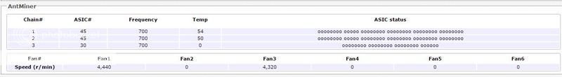
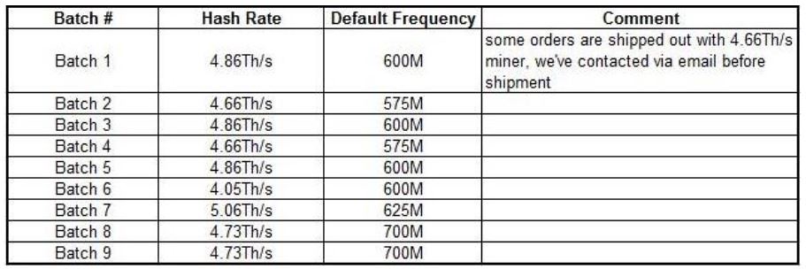