 Show Posts Show Posts
|
|
Pages: [1]
|
Ⅰ. Требования к подготовке ремонтной платформы/инструментов/оборудования 1. Требования к платформе: Антистатическое рабочее место для обслуживания (рабочее место необходимо заземлить), антистатический браслет и заземление. 2. Требования к оборудованию: (1) Паяльник с постоянной температурой (350°C-380°C), заостренный наконечник паяльника используется для пайки небольших участков, таких как чип-резисторы и конденсаторы; (2) Термофен и ремонтная станция BGA используются для разборки и сварки чипов/BGA; (3) Мультиметр с приваренными стальными штифтами и термоусадочными втулками для удобства измерения (рекомендуется мультиметр Fluke 15b+); (4) Осциллограф (рекомендуется осциллограф UTD2102CEX+), сетевой кабель (требования: подключение к Интернету, стабильная сеть) 3. Требования к тестовому инструменту: (1) Источник питания APW12: AP12_12V-15V_V1.2 и кабель адаптера питания (сделанный самостоятельно: используйте толстый медный провод для положительного и отрицательного полюсов источника питания для подключения источника питания и платы питания, рекомендуется использовать Медный провод 4AWG длиной менее 60 см, ограниченный только PT1 и использованием для проверки технического обслуживания), используемый для питания хеш-платы; (2) Используйте тестовое приспособление платы управления V2.3 (номер материала испытательного приспособления ZJ0001000001). Положительный и отрицательный полюсы испытательного приспособления необходимо установить с разрядными резисторами. Рекомендуется использовать цемент с сопротивлением 20 Ом и мощностью 100 Вт или более. 4. Требования к вспомогательным материалам/инструментам для обслуживания: (1) Паяльная паста 138°C, флюс, бессвинцовый очиститель печатных плат Mechanic и безводный спирт; (2) Механический бессвинцовый очиститель печатных плат используется для очистки остатков флюса после технического обслуживания; (3) На поверхность чипа после ремонта наносится теплопроводящий гель; (4) Стальная сетка для посадки шариков, демонтажный фитиль и шарики припоя (рекомендуемый диаметр шарика 0,4 мм); (5) При замене нового чипа необходимо залудить контакты чипа, а затем припаять их к хеш-плате. Равномерно нанесите теплопроводный гель на поверхность чипа, а затем зафиксируйте радиатор. (6) Сканер кода последовательного порта. (7) Плата адаптера последовательного порта RS232 на плату адаптера TTL 3,3 В. (8 ) Самодельный датчик короткого замыкания (используйте штифты для проводки и сварки, и необходимо нагреть термоусадочную втулку, чтобы предотвратить короткое замыкание между датчиком и небольшим радиатором). 5. Общие требования к запасным материалам для технического обслуживания: Резистор 0402 (0Р, 51Р, 10К, 4,7К,); Конденсатор 0402 (0,1мкФ, 1мкФ) Ⅱ. Требования к техническому обслуживанию 1. Обратите внимание на метод работы при замене чипа. После замены каких-либо аксессуаров печатная плата не имеет явных деформаций. Проверьте запасные части и окружающие детали на отсутствие недостающих частей, обрывов цепи и коротких замыканий. 2. Обслуживающий персонал должен обладать определенными знаниями в области электроники, иметь опыт обслуживания более одного года и владеть технологиями упаковки BGA/QFN/LGA и сварки. 3. После ремонта хэш-доску необходимо протестировать более двух раз, и все в порядке! 4. Проверьте инструменты, может ли тестовое приспособление нормально работать, определите параметры тестового программного обеспечения станции технического обслуживания, версию тестового приспособления и т. д. 5. Для проверки ремонта и замены чипа необходимо сначала протестировать чип, а затем выполнить функциональный тест после прохождения. Функциональный тест должен убедиться, что малый радиатор приварен нормально, а большой радиатор установлен на место (каждый гель термоклея должен быть нанесен равномерно, а затем установлен большой радиатор), а охлаждающий вентилятор работает на полной скорости. При использовании шасси для отвода тепла следует размещать одновременно две хеш-панели, образующие воздуховод. Односторонний тест производства также должен гарантировать, что воздуховод сформирован (Важно) 6. При измерении сигнала помогите 4 вентиляторам рассеивать тепло, чтобы вентиляторы продолжали работать на полной скорости. 7. Когда хеш-плата включена, сначала должен быть подключен отрицательный медный провод источника питания, затем должен быть подключен положительный медный провод источника питания, и, наконец, должен быть вставлен сигнальный кабель. При разборке порядок установки должен быть обратным. Сначала отсоедините сигнальный кабель, затем отсоедините положительный медный провод источника питания и, наконец, отсоедините отрицательный медный провод источника питания. Если не соблюдать этот порядок, очень легко повредить U1 и U2 (не все фишки можно найти). Перед тестированием Pattern отремонтированная хеш-плата должна быть охлаждена перед тестированием, иначе это приведет к тестированию PNG. 8. Чтобы заменить новый чип, очистите контакты и припойную пасту, чтобы убедиться, что чип предварительно залужен, а затем припаян к печатной плате для ремонта. 9. Все тестовые приспособления на стороне обслуживания тестируются в режиме Test_Mode и в режиме кода сканирования. После прохождения теста производственная сторона будет оптимизирована с первой тестовой станции, а обычная установка будет устаревшей (установлена в соответствии с тем же уровнем). Ⅲ. Производство испытательных приспособлений и меры предосторожности Испытательное приспособление должно удовлетворять требованиям по рассеиванию тепла рабочей платой, чтобы облегчить измерение сигналов. 1. Получите номер детали: испытательное приспособление ZJ0001000001. 2. В первый раз используйте SD-карту тестового приспособления серии 19, чтобы провести программу для обновления FPGA платы управления тестовым приспособлением. После распаковки скопируйте его на SD-карту и вставьте карту в слот для карты тестового приспособления; подождите около 1 минуты после включения питания и подождите, пока индикатор платы управления не мигнет 3 раза дважды, это означает, что обновление завершено; (если он не обновлен, это может привести к тому, что определенный чип будет признан неисправным во время теста). https://www.zeusbtc.com/share/antminer-d7-hash-board-repair-guide/indicator-light.jpg3. Сделайте тестовую SD-карту в соответствии с требованиями, односторонний радиатор обнаруживает чип и непосредственно распаковывает сжатый пакет, чтобы сделать SD-карту; PT1 не нужно сканировать код; версия программного обеспечения D7_PT1_test_zhiju_20210827. Скопируйте следующие файлы на SD-карту, производство завершено. https://www.zeusbtc.com/share/antminer-d7-hash-board-repair-guide/pt1-software-file.jpg4. Сделайте тестовую SD-карту в соответствии с требованиями. Двухсторонний тест радиатора 8x Pattern должен сделать SD-карту, как показано на рисунке ниже; тест PT2 должен быть вставлен с кодовым пистолетом и сетевым кабелем. Версия программного обеспечения является версией программного обеспечения PT2, скопируйте следующее содержимое на SD-карту, чтобы завершить производство; https://www.zeusbtc.com/share/antminer-d7-hash-board-repair-guide/pt2-software-file.jpg5. При использовании двустороннего теста 8x Pattern на стороне производства, на стороне внутренних продаж и на стороне аутсорсингового обслуживания требуется соответствующий сканер кода и инструменты последовательного порта. Подробности см. в руководстве по тестированию D7. Ⅳ. Обзор принципа 1. Рабочая структура хеш-платы D7: Хэш-плата D7 состоит из 70 чипов Antminer BM1764, которые разделены на 35 доменов, и каждый домен состоит из 2 чипов ASIC; рабочее напряжение микросхем BM1764, используемых в хеш-плате D7, составляет 0,3В; Выходное напряжение 20 В повышающей схемы U238 выводится линейным регулятором (U295 U16 U14 U307 U310 U313) для подачи 1,8 В на группы 29, 30, 31, 32, 33, 34 (всего 6 групп) для обеспечения LDO Источник питания 1,8 В, 1,8 В для LDO (U294 U15 U13 U306 U309 U312 U187 U188 U190 U191 U193 U194) выход 0,8 В. 28-я группа - 1-я группа и 35-я группа обеспечиваются VDD 13 В через LDO для обеспечения 1,8 В, 1,8 В, а затем через линейный регулятор для обеспечения 0,8 В, напряжение домена составляет около 0,3 В. Как показано на рисунке: Группа 28 - Группа 1 и Группа 35 https://www.zeusbtc.com/share/antminer-d7-hash-board-repair-guide/domain-voltages-for-groups-1-and-35.jpgГруппы 29-34 https://www.zeusbtc.com/share/antminer-d7-hash-board-repair-guide/domain-voltages-for-groups-29-to-34.jpghttps://www.zeusbtc.com/share/antminer-d7-hash-board-repair-guide/d7-hash-board-chip-location.jpghttps://www.zeusbtc.com/share/antminer-d7-hash-board-repair-guide/d7-hash-board-voltage-domain.jpg2. Схема повышения хеш-платы BXD34601: Буст питается от 13В от блока питания и превращается в 20В, как показано на рисунке. https://www.zeusbtc.com/share/antminer-d7-hash-board-repair-guide/d7-boost-circuit-location.jpghttps://www.zeusbtc.com/share/antminer-d7-hash-board-repair-guide/d7-boost-circuit-schematic.jpg3. Направление сигнала чипа D7: (1) Поток сигнала CLK (XIN) генерируется кварцевым генератором Y2 25 МГц и передается от чипа № 01 к чипу № 70; напряжение около 0,9В; (2) Поток сигналов RST и CI поступает с 3-го контакта (3,3 В) J3 и преобразуется микросхемой преобразования уровней U1-U3-U4, а затем передается с микросхемы № 01 на микросхему № 70; (3) Направление потока сигнала RX (RI, RO) от чипа № 70 к чипу № 01 и возвращается к контакту 8 разъема сигнального кабеля через U2, а затем возвращается к плате управления; 4) поток сигналов БО (БИ, ВО), от микросхемы № 01 к № 70; 4. Вся структура майнера: Весь майнер в основном состоит из 3 хеш-плат, 1 платы управления Antminer D7, блока питания APW12 и 4 охлаждающих вентиляторов, как показано на рисунке: https://www.zeusbtc.com/share/antminer-d7-hash-board-repair-guide/d7-miner-architecture.jpgⅤ. Распространенные проблемы и шаги по устранению неполадок с хэш-доской Явление 1: тест одной платы обнаруживает, что чип равен 0 (станция PT1/PT2) Первый шаг: сначала проверьте выходную мощность, пожалуйста, проверьте напряжение в обведенной части на рисунке ниже. https://www.zeusbtc.com/share/antminer-d7-hash-board-repair-guide/power-output-schematic.jpghttps://www.zeusbtc.com/share/antminer-d7-hash-board-repair-guide/check-the-circle-area-voltage.jpgВторой шаг: проверьте выходное напряжение домена напряжения Напряжение каждого домена напряжения составляет около 0,3 В, а источник питания 13 В обычно имеет напряжение домена. Приоритет отдается измерению выходного сигнала клеммы питания хеш-платы, а также проверке наличия короткого замыкания МОП (измерьте сопротивление резистора между контактами 1, 4 и 8 ). Если питание 13В есть, но напряжения домена нет, продолжайте проверку. https://www.zeusbtc.com/share/antminer-d7-hash-board-repair-guide/mos-chip-location.jpgТретий шаг: проверьте цепь PIC Измерьте, имеет ли контакт 11 U6 выход (3,3 В). Если да, продолжайте устранять проблему. Если нет, убедитесь, что соединение между кабелем тестового приспособления и хэш-платой в порядке, и перепрограммируйте PIC. https://www.zeusbtc.com/share/antminer-d7-hash-board-repair-guide/pic-circuit-schematic.jpghttps://www.zeusbtc.com/share/antminer-d7-hash-board-repair-guide/pic-location.jpgШаги программирования PIC: (1) Запишите программу PIC хеш-платы. Загрузите инструмент программирования: программатор PICkit3.5, контакт 1 кабеля PICkit3 соответствует контакту 1 J3 на печатной плате и должен быть подключен к контактам 1, 2, 3, 4, 5 и 6. https://www.zeusbtc.com/share/antminer-d7-hash-board-repair-guide/pickit3-programming-tool.jpg(2) Программное обеспечение для записи: ① Откройте MPLAB IPE, выберите устройство: PIC16F1704; ② Нажмите «Power», чтобы выбрать способ подачи питания, а затем нажмите «Operate»; ③ Выберите file, чтобы найти файл .HEX для записи; ④ Нажмите «connect», подключение нормальное. ⑤ Нажмите кнопку «Program». ⑥ После завершения нажмите «Verifiy», чтобы подтвердить успешность записи. https://www.zeusbtc.com/share/antminer-d7-hash-board-repair-guide/mplab-ipe-software.jpghttps://www.zeusbtc.com/share/antminer-d7-hash-board-repair-guide/mplab-ipe-running-interface.jpgЧетвертый шаг: проверьте выход схемы усилителя и проверьте C69 на следующем рисунке, и напряжение может быть измерено до 20 В. https://www.zeusbtc.com/share/antminer-d7-hash-board-repair-guide/measured-to-boost-circuit-20v-voltage.jpgПятый шаг: проверьте каждую группу выхода LDO 1,8 В или PLL 0,8 В. Группа 28 - Группа 1 и Группа 35 https://www.zeusbtc.com/share/antminer-d7-hash-board-repair-guide/group-28-ldo-and-pll-voltage-outputs.jpgГруппы 29-34 https://www.zeusbtc.com/share/antminer-d7-hash-board-repair-guide/groups-29-34-ldo-and-pll-voltage-outputs.jpgШестой шаг: проверьте вывод сигнала чипа (CLK/CI/RO/BI/RST) Диапазон значений напряжения описывается направлением опорного сигнала. Если при измерении обнаруживается большое отклонение значения напряжения, его можно сравнить со значением измерения соседней группы. https://www.zeusbtc.com/share/antminer-d7-hash-board-repair-guide/chip-test-point-signal-schematic.jpgКогда на ЖК-экране тестового приспособления отображается EEPROM NG, проверьте, нормально ли припаян U10; https://www.zeusbtc.com/share/antminer-d7-hash-board-repair-guide/u10-voltage-schematic.jpgКогда датчик PIC NG отображается на ЖК-экране тестового приспособления, температура показаний теста не соответствует норме. Для устранения неполадок выполните следующие действия: а) Проверьте, н |
|
|
|
Ⅰ. Preparation requirements for maintenance platform/tools/equipment 1. Platform requirements: Static repair workbench (workbench needs to be grounded), anti-static wristband and grounding. 2. Equipment requirements: (1) Constant temperature soldering iron (350°C - 380°C), pointed soldering iron tip is used to solder small patches such as chip resistors and capacitors; (2) Hot air gun and BGA rework station are used for chip / BGA disassembly and welding; (3) Multimeter, with welded steel needles and heat-shrinkable sleeves for easy measurement (Fluke 17B+ multimeter is recommended); (4) Oscilloscope, network cable 3. Test tool requirements: (1) APW12 power supply: APW12_14V-17V_V1.2 and power adapter cable, used for hash board power supply; (2) Test fixture, material number is ZJ0001000001.The positive and negative poles of the power supply of the test fixture need to be installed with discharge resistors. It is recommended to use a cement resistance of 20 ohms, 100W or more. 4. Maintenance auxiliary materials/tools requirements: (1) Solder paste thousand pillars M705, flux, board washing water and anhydrous alcohol; (2) Board washing water is used to clean up the flux residue after repair; (3) Thermally conductive gel (specification: Fujipoly SPG- 30B) is used to apply on the chip surface after repair; (4) Ball-planting steel mesh, solder-absorbing wire, and solder balls (ball diameter is recommended to be 0.4mm); (5) When replacing a new chip, it is necessary to tin the chip pin and then solder it to the hash board. Apply thermal conductive gel evenly on the chip surface and then lock the heat sink. (6) Serial port code scanner. (7) Serial port adapter board RS232/TTL adapter board 3.3V ( 8 ) Self-made short-circuit probe (use the pins to wire and solder, and need to heat the shrinkable sleeve to prevent short-circuit between the probe and the small heat sink) 5. Common maintenance spare material requirements: 0402 Resistor (0R, 1K, 4.7K, 10K, ); 0402 Capacitor (0.1uF, 1uF) Ⅱ. Repair requirements 1. Pay attention to the operation method when replacing the chip. After replacing any accessories, the PCB board has no obvious deformation. Check the replaced parts and the surrounding for missing parts, open circuits and short circuits. 2. Maintenance personnel must have certain electronic knowledge, more than one year of maintenance experience, and be proficient in BGA/QFN/LGA packaging and welding technology. 3. After maintenance, the hash board must be tested more than two times and all are OK before passing! 4. Check whether the tools and test fixtures can work normally, determine the parameters of the maintenance station test software, and the version of the test jig. 5. For the test of repairing and replacing the chip, it is necessary to test the chip first, and then do the functional test after pass. The functional test must ensure that the small heat sink is welded OK and the large heat sink is installed in place (each thermal adhesive must be applied evenly and then the large heat sink is installed), And the cooling fan is at full speed. When using the chassis to dissipate heat, two computing boards should be placed at the same time to form an air duct. The single-sided test of the production should also ensure that the air duct is formed (important). 6. Assist 4 fans to dissipate heat when measuring signals, and keep the fans at full speed. 7. When the hash board is powered on, the negative copper wire of the power supply must be connected first, then the positive copper wire of the power supply must be connected, and finally the signal cable must be inserted. When disassembling, the order of installation must be reversed. First, remove the signal cable, then remove the positive copper wire of the power supply, and finally remove the negative copper wire of the power supply. If you do not follow this order, it is very easy to cause damage to U1 and U2 (not all chips can be found). Before testing the pattern, the repaired hash board must be cooled down before testing, otherwise it will result in testing PNG. 8. When replacing a new chip, tin the chip pins to ensure that the chip is pre-tinned and then soldered to the PCBA for maintenance. III. Test fixture making and matters needing attention The test fixture matching fixture should meet the heat dissipation of the hash board, which is convenient for signal measurement. 1. Get the part number: ZJ0001000001 Test fixture. It is also recommended to use the new version of the digital display Antminer test fixture. 2. Use the 7Z007 series test fixture SD card swipe program for the first time to update the FPGA of the fixture control board, decompress it and copy it to the SD card, insert the SD card into the test fixture card slot; power on for about 1 minute and wait for the control board indicator lights to double flash at least 3 times, the update is completed; if it is not updated, it may cause a certain chip to be reported as bad during the test. https://www.zeusbtc.com/share/antminer-l7-hash-board-repair-guide/indicator-light.jpg3. Make the test SD card according to the requirements. The single-sided heat sink inspection chip can be directly decompressed and compressed to make the SD card; when PT1 is tested, the network cable is not inserted and the code scanner is not inserted. https://www.zeusbtc.com/share/antminer-l7-hash-board-repair-guide/sd-card-compressed-package.jpg4. Make the test SD card according to the requirements. The PT2 needs to make the SD card to run the Patter test, as shown in the figure below; the PT2 test needs to insert the code scanning gun and the network cable. https://www.zeusbtc.com/share/antminer-l7-hash-board-repair-guide/pt2-runs-the-patter-test-archive.jpg5. Special attention: PT1 & PT2 are separate test programs, and there is no need to modify the Config file. The production end, after-sales end, and outsourcing repari PT2 need to support the scanning gun and serial port tools when testing the Pattern. See L7 test process document for details. IV. Principle overview 1. Working structure of L7 hash board: The hash board is composed of 120 BM1489 chips, which are divided into 24 domains, and each domain is composed of 5 ASIC chips; the working voltage of the BM1489 chips used by the L7 hash board is 0.6V; The 24th, 23rd, 22nd, 21st groups (4 groups in total) are powered by the 19.6V output from the boost circuit U13 to the LDO (U249 U247 U243 U239), so that the LDOs of these 4 domains output 1.8V and 0.8V. The power supply of the 20th group LDO is powered by VDD 14.4V to the 20th domain LDO, so that it outputs 1.8V and 0.8V, and the domain voltage is reduced by 0.6V each domain back. As shown in figure: https://www.zeusbtc.com/share/antminer-l7-hash-board-repair-guide/l7-hash-board-voltage-domain.jpghttps://www.zeusbtc.com/share/antminer-l7-hash-board-repair-guide/l7-hash-board-voltage-domain-schematic.jpghttps://www.zeusbtc.com/share/antminer-l7-hash-board-repair-guide/l7-hash-board-domain-trend.jpghttps://www.zeusbtc.com/share/antminer-l7-hash-board-repair-guide/l7-hash-board-voltage-domain-trend.jpg2. Boost circuit of L7 hash board: The boost circuit of the L7 hash board is 15V provided by the power supply, and converted to 19.6V, as shown in the figure. https://www.zeusbtc.com/share/antminer-l7-hash-board-repair-guide/l7-hash-board-boost-circuit.jpghttps://www.zeusbtc.com/share/antminer-l7-hash-board-repair-guide/l7-hash-board-boost-circuit-schematic.jpg3. Signal direction of L7 chip: (1) The CLK signal flow direction is generated by Y1&Y2 25M crystal oscillator, Y1 provides chips from No. 01 to No. 60; Y2 provides chips from No. 61 to No. 120, and the voltage measured by the multimeter is about 0.8V-0.9V; (2) The RST and CI signals flow from the IO port 3 pin (3.3V) into the level conversion IC U1-U3-U4 after conversion, and then from the 01 chip to the 120 chip transmission; when the IO line is not inserted, the voltage is 0V, the voltage during operation is 1.8V; (3) RX (RI, RO) signal flow direction, from chip No. 120 to chip No. 01, through U1 back to pin 8 of the signal cable terminal and back to the control board; when the IO signal is not inserted, the voltage is 0.3V, and the voltage during operation is 1.8 V; (4) BO (BI, BO) signal flow, from chip No. 01 to No. 120; the multimeter measures it as 0V; 4. The whole Antminer L7 structure: The whole Antminer L7 is mainly composed of 3 hash boards, 1 control board, APW12 power supply, and 4 cooling fans, as shown in Figure. https://www.zeusbtc.com/share/antminer-l7-hash-board-repair-guide/l7-miner-architecture.jpgⅤ. Common bad phenomena of the hash board and troubleshooting steps Phenomenon 1: The single-board test detects that the chip is 0 (PT1/PT2 station) First step: check the output of the power supply, please check the part of the voltage circled in the picture. https://www.zeusbtc.com/share/antminer-l7-hash-board-repair-guide/schematic-diagram-of-power-supply-voltage-output.jpgSecond step: check the voltage domain voltage output The voltage of each voltage domain is about 0.6V, and the 15V power supply generally has the domain voltage. Priority is given to measuring the output of the power supply terminal of the hash board, and whether the MOS is short-circuited (measure the resistor value between pins 1, 4, and 8 ). If 15V is powered but there is no domain voltage, continue to troubleshoot. https://www.zeusbtc.com/share/antminer-l7-hash-board-repair-guide/mos-tube-voltage-domain.jpgThird step: check the PIC circuit Measure whether the pin 11 of U6 has output, the voltage is about 3.2V, if there is, please continue to troubleshoot the problem, if there is no 3.2V, please check the connection status of the test fixture cable and the hash board is OK, and re-program the PIC. https://www.zeusbtc.com/share/antminer-l7-hash-board-repair-guide/pic-circuit-schematic.jpgPIC programming steps: ① Burn the PIC program of the hash board. Program: 20200101-PIC1704-BM1398-V89.hex Download the programming tool: PICkit3, pin 1 of the PICkit3 cable corresponds to pin 1 of J3 on the PCB board, and needs to be connected to pins 1, 2, 3, 4, 5, and 6. https://www.zeusbtc.com/share/antminer-l7-hash-board-repair-guide/pickit3.jpg② Burning software: (1) Open MPLAB IPE, select device: PIC16F1704, click power to select the power supply mode. (2) Click operate, select file to find the .HEX file to be burned; click connect, the connection is normal; click the program button, and click "verifiy" after completion, and the verification is completed to prove that the burning is successful. https://www.zeusbtc.com/share/antminer-l7-hash-board-repair-guide/mplab-ipe-burning-software.jpghttps://www.zeusbtc.com/share/antminer-l7-hash-board-repair-guide/mplab-ipe-running-interface.jpgFourth step: check the boost circuit output Measure C70 in figure whether the voltage is 23V. https://www.zeusbtc.com/share/antminer-l7-hash-board-repair-guide/boost-circuit-23v-voltage.jpghttps://www.zeusbtc.com/share/antminer-l7-hash-board-repair-guide/boost-circuit-working-voltage.jpgFifth step: check each group of LDO 1.8V or PLL 0.8V output https://www.zeusbtc.com/share/antminer-l7-hash-board-repair-guide/ldo-and-pll-test-points.jpghttps://www.zeusbtc.com/share/antminer-l7-hash-board-repair-guide/ldo-and-pll-circuit-schematic.jpgSixth step: check the chip signal output (CLK/CI/RI/BO/RST) The voltage value range described by the reference signal direction, if the measurement encounters a large deviation of the voltage value, it can be compared with the measurement value of the adjacent group. https://www.zeusbtc.com/share/antminer-l7-hash-board-repair-guide/schematic-diagram-of-chip-signal-output.jpgPhenomenon 2: The single-board detection lacks the chip (PT1/PT2 station) a) LCD screen displays ASIC NG: (0), first measure the total voltage of the domain and the boost circuit 23V is normal, then use a short-circuit probe to short-circuit the RO test point and the 1V8 test point between the 1st and 2nd. Then run the Find Chip program. Looking at the serial port log, if 0 chips are still found at this time, it will be one of the following situations: a-1) Use a multimeter to measure whether the voltages of the 1V8 and 0V8 test points are 1.8V and 0.8V. If not, it may be that the 1.8V and 0.8V LDO circuits in this domain are abnormal, or two ASIC chips in this domaina are not soldered well, most of them are caused by short circuit of 0.8V and 1.8V chip filter capacitors (measure the resistance value of chip filter capacitors related to the front and back of PCBA) a-2) Check whether the circuits of U1 and U2 are abnormal, such as resistance soldering, etc. a-3) Check whether the first chip has pins that are not soldered well (it was found during maintenance, the pins are tin from the side, but they are removed The chip found that the pins were not tinned at all) b) If one chip can be found in step a), it means that the first chip and the previous circuit are all good. Use the similar method to check the following chips. For example, short-circuit the 1V8 test point and the RO test point between the 38th and 39th chips. If the log can find 38 chips, the first 38 chips are no problem; if 0 chips are still found, check whether the 1V8 is normal first? If it is normal, there is a problem with the chips after 38. Continue to dichotomize until you find the chip in question. Suppose there is a problem with the Nth chip, then when the 1V8 and RO between the N-1th and Nth chips are short-circuited, the N-1 chip can be found. But when 1V8 and RO between the Nth and N+1th chips are short-circuited, not all chips can be found. c) LCD display X ASIC NG: When a certain chip is fixedly reported, the value of the chip reported in each test usually does not change. In this case, the repair method can be carried out according to the maintenance method of measuring the signal voltage normally. https://www.zeusbtc.com/share/antminer-l7-hash-board-repair-guide/l7-chip-signal-test-point.jpgPhenomenon 3: Single board Pattern NG, that is, the reply nonce data is incomplete (PT2 station) Pattern NG is caused by the large difference between the characteristics of the chip and other chips, so just replace the chip. According to the screen prompt of the test fixture or the log information, the replacement rule is: if the appearance of the chip is not damaged, replace the chip with the lowest reply rate in each domain. The following picture shows one of the test logs. It can be seen from the fixture display that the reply rate of the four chips of asic[10][41][69][75] is low. 69 and 70 are in the same domain, so replace the one with the lowest nonce in 69 and 70. Replace the 10 and 41 at the same time. PS: need to pay special attention, the number of domain and asic starts from 0, note that the abnormal voltage of the domain will also cause insufficient response of the chip nonce. https://www.zeusbtc.com/share/antminer-l7-hash-board-repair-guide/test-failed-showing-chip-page.jpgPhenomenon 4: No chip is broken, but the reply rate is not up to standard, and the fixture screen displays P:NG. P: NG is because some of the chips have a poor reply. You can check the log to replace the 2 with the lowest reply, so that the overall reply rate can reach the standard. https://www.zeusbtc.com/share/antminer-l7-hash-board-repair-guide/no-chip-display-page.jpghttps://www.zeusbtc.com/share/antminer-l7-hash-board-repair-guide/domain-voltage-is-low.jpgNote: Abnormal domain voltage will also cause insufficient response of chip nonce. Phenomenon 5: Sensor NG https://www.zeusbtc.com/share/antminer-l7-hash-board-repair-guide/test-fixture-sensor-ng-page.jpgMaintenance method: When testing PT1 & PT2, look at the serial port print log, confirm that the temperature sensor reports an error, and check the temperature sensor circuit accordingly; first measure whether the power supply of the 8th pin of the temperature sensor is 3.3V, and then check whether the SDA and SCL buses are abnormal. Requirements for the PT2 test environment: The temperature of the PT2 test environment should be between 25℃ and 30℃. When the ambient temperature is below 25℃, the software will stop the test. PT2 test power supply requirements: When the PT2 test fixture power supply is under a load of 1500 watts (in the case of testing a board), the actual output voltage cannot be lower than the 0.03V set in the configuration file. (For example, the configuration file requires an output of 13.8V, then the output voltage of the power supply cannot be lower than 13.77V when it is loaded with 1500 watts) Ⅵ. Control board problems cause the following problems 1. The whole miner does not work 1) Check whether the voltage of several voltage output points is normal, 3.3V short circuit can disconnect U8 first, if it is still short circuit, unplug the CPU and measure. For other abnormal voltages, generally replace the corresponding converter IC. 2) If the voltage is normal, please check the welding condition of the DDR/CPU (X-RAY check on the production side) 3) Try to update the flash program with SD card; If the miner with the control board card swiping needs to start normally, the following steps are required: a) After the card is swiped successfully, the green LED indicator is always on, and the power is turned off and restarted; b) Wait for 30s after powering on again (time course of opening OTP) c) OTP (One Time Programable) is a memory type of MCU, which means one-time programmable: after the program is burned into the IC, it cannot be changed or cleared again; Precautions: (1) Sudden power failure during the OTP opening process or the time is less than 30s will cause the control board to fail to open the OTP function, the control board will not start (not connected to the Internet), and the U1 (control board main control IC FBGA) needs to be replaced. U1 can no longer be used on 19 series; (2) U1 cannot be used on other series of models if the control board with OTP function is turned on; https://www.zeusbtc.com/share/antminer-l7-hash-board-repair-guide/l7-control-board.jpg2. The whole miner cannot find the IP There is a high probability that the IP cannot be found due to abnormal operation. Refer to point 1 for troubleshooting. Check the appearance and welding condition of the network port, network transformer T1, and CPU. 3. The whole miner cannot be upgraded Check the appearance and welding condition of the network port, network transformer T1, and CPU. 4. The whole miner fails to read the hash board or the chain is missing A. Check the cable connection. B. Check the parts of the control board corresponding to the chain. C. Check the wave soldering quality of the header pins and the resistance around the plug-in interface. https://www.zeusbtc.com/share/antminer-l7-hash-board-repair-guide/plugin-interface.jpgⅦ. The whole miner failure phenomenon 1. Preliminary test of the whole machine Referring to the test process document, the general problems are assembly process problems and control board process problems. Common phenomenon: IP cannot be detected, abnormal number of fans detected, abnormal detected chain. If there is an abnormality during the test, it should be repaired according to the monitoring interface and the test LOG prompts. The maintenance methods of the initial test and the aging test of the whole machine are the same. https://www.zeusbtc.com/share/antminer-l7-hash-board-repair-guide/test-results-page.jpg2. Aging test: the old test should be repaired according to the monitored interface test, such as; 1) The fan display is abnormal - we have to check whether the fan works normally, whether the connection with the control board is normal, and whether the control board is abnormal. 2) Less chain: Less chain means that 3 boards are missing 1 board. In most cases, there is a problem with the connection between the hash board and the control board. Check the cable to see if there is an open circuit. If the connection is OK, you can test the board to PT2 to see if it can be tested. If it can be tested, it can basically be determined that it is the control board. If the test fails, use the repair method of PT2 maintenance. 3) Abnormal temperature: Generally, the temperature is high. The maximum PCB temperature set by our monitoring system cannot exceed 90 ℃. The fan will alarm and it will not work normally. Generally, the ambient temperature is too high, and the abnormal operation of the fan will also cause abnormal temperature. 4) Can not find all the chips (the same can be turned on, but the computing power is 2/3 or 1/3 of the normal value) The number of chips is not enough: If the number of chips is not enough, you can refer to PT2 for testing and repair. https://www.zeusbtc.com/share/antminer-l7-hash-board-repair-guide/detect-0-chips.jpg5) After running for a period of time, there is no hashrate, and the connection of the mining pool is interrupted, check the network; https://www.zeusbtc.com/share/antminer-l7-hash-board-repair-guide/network-connection-lost.jpg6) The aging test state of the normal good miner; https://www.zeusbtc.com/share/antminer-l7-hash-board-repair-guide/l7-miner-aging-test-status.jpgVIII. Other Precautions Maintenance flow chart https://www.zeusbtc.com/share/antminer-l7-hash-board-repair-guide/l7-miner-maintenance-flow-chart.jpg1. Routine testing: First, visually inspect the hash board to be repaired to observe whether there is any PCB deformation or scorching. If there is, it must be dealt with first; Whether any parts have obvious burn marks, parts impact offset or missing parts, etc.; Secondly, after the visual inspection is no problem, you can first detect the impedance of each voltage domain, whether there is a short circuit or an open circuit. If found, it must be dealt with in advance. Then, check whether the voltage of each domain is about 0.6V. 2. After the routine inspection is OK (generally the short-circuit inspection of the routine inspection is necessary to avoid burning the chip or other materials due to short-circuit when the power is turned on), the chip can be inspected with a test fixture, and the positioning is determined according to the test results of the test fixture. 3. According to the display results detected by the test fixture, starting from the vicinity of the faulty chip, check the chip test points (CI/NRST/RO/XIN/BI), and the voltages of VDD 0V8 and VDD 1V8. 4. Then according to the signal flow, except for the reverse transmission of the RX signal (chips 120 to 1), the other signals CLK, CI, BI, and RST are transmitted in the forward direction (chips 1 to 120). Through the power supply sequence, find unusual points of failure. 5. When the faulty chip is located, the chip needs to be re-soldered. The method is to add flux (preferably no-clean flux) around the chip, heat the solder joints of the chip pins to a dissolved state, and promote the chip pins and pads to re-grind and collect tin. In order to achieve the effect of re-tinning. If the fault is still the same after re-soldering, the chip can be replaced directly. 6. After repairing the hash board, when using the test fixture to test, it must pass more than two times to be judged as normal. After the replacement parts are completed, wait for the hash board to cool down. After using the test fixture for the first time to test the pass, put it aside before cooling. Wait a few minutes for the hash board to cool completely before doing the second test. 7. After the hash board is repaired OK. Relevant maintenance/analysis records need to be made (requirements for maintenance reports: date, SN, PCB version, tag number, cause of failure, attribution of responsibility for failure, etc.). In order to feedback back to production, after-sales, and research and development. 8. After the document recording is completed, it is then assembled into a complete machine for routine aging. 9. The good products repaired on the production side should be streamlined from the first station of production (at least the appearance inspection and the PT1/PT2 test station)! 10. The repaired defective hash board, the thermal conductive gel must be removed, and the large heat sink should be repainted before it can be streamlined! |
|
|
|
When repairing a single hash board of Avalon 10 series, if the test fixture reports 0 or a number, no matter whether the C signal and the CK signal are normal or not, you can use the Avalon debug signal short circuit board to quickly locate the faulty chip. Avalon debug D signal shorting board is suitable for A10 series, A11 series, A12 series. When in use, you only need to press the switch, short-circuit the clip to connect to the D signal on the board, and you can replace the oscilloscope to find the fault point, which is very convenient. Avalon debug D signal shorting board structure description: https://www.zeusbtc.com/share/avalon-d-signal-short-circuit-board/avalon-debug-d-signal-short-circuit-board-interface.jpg1. Short-circuit the positive pole, connect the D signal test point that the chip needs to be short-circuited 2. Short-circuit the negative pole, connect the negative pole of the power supply where the chip signal to be short-circuited is located, which is the domain voltage Vcore) 3. Test fixture cable interface (two data interfaces) 4. Hash board cable interface (two data interfaces) 5. Pull the switch: Open: The normal test mode is the same as the function when the fixture is not connected to this small board. Press: short-circuit search mode, find the number of chips through the short-circuit clip (the cable should also be connected to the hash board) 6. Short-circuit clip interface 7. Data cable 8. 12V power interface https://www.zeusbtc.com/share/avalon-d-signal-short-circuit-board/short-circuit-board-connection-physical-diagram.jpgAvalon debug D Signal Shorting Board Instructions for Use: 1. When the Avalon board test shows asic count: 0; First, connect the D signal short circuit board to the Avalon hash board as shown above, press the switch on the short circuit board, and the shorting clip randomly shorts the D signal from the D signal transmission direction to locate the faulty chip. https://www.zeusbtc.com/share/avalon-d-signal-short-circuit-board/hash-board-test-result.jpg2. When the Avalon single board test shows asic count: 10, it means that the hash board lacks chips; https://www.zeusbtc.com/share/avalon-d-signal-short-circuit-board/short-circuit-d-signal.jpgShort-circuit the D signal output by the A16 chip, and the test fixture displays asic count: 10. It should be noted that the correct number of chips is 16-6=10 because there are no soldered chips in the first 6 A1-A6 positions of the test board. At this time, the number reported in the log is the same as the number of chips before the short-circuit signal, indicating that the first 10 chips are normal. Therefore, we need to continue the short circuit check until we find the chip without a D signal to locate the faulty chip. |
|
|
|
|
Das Antminer Test Fixture wird hauptsächlich verwendet, um den fehlerhaften Chip des Hashboards zu testen. Es scannt Unterbrechungen und Kurzschlüsse, Widerstände, Kondensatoren, Induktivitäten, Dioden, Trioden, Transistoren, ICs und andere Komponenten des gesamten Hash-Boards, indem es ein Baudratensignal sendet.
Verschiedene Antminer-Modelle entsprechen verschiedenen Antminer-Testvorrichtungen.
Die Antminer-Chiptestvorrichtung lokalisiert den Hash-Board-Chip genau, um Fehler wie Lötkurzschluss, falsches Einsetzen von Komponenten, umgekehrtes Einsetzen, fehlende Installation, Stiftabheben, virtuelles Schweißen, Leiterplattenkurzschluss, Trennung und andere Fehler zu finden. Die getesteten Fehler befinden sich direkt an bestimmten Komponenten und Stiften, und die Fehlerstelle ist genau. Darüber hinaus übernimmt die Testvorrichtung programmgesteuerte automatisierte Tests, die einfach zu bedienen und schnell zu testen sind. Die Testzeit eines einzelnen Hash-Boards liegt im Allgemeinen zwischen einigen Sekunden und mehreren zehn Sekunden, und die Scanergebnisse können direkt auf der Seite angezeigt werden, wodurch die Möglichkeit manueller Eingabefehler vermieden wird.
Was sind die Arbeitsprinzipien der Antminer-Testvorrichtung?
Die Antminer-Testvorrichtung erkennt fehlerhafte Chips, indem sie das Hash-Board sequentiell mit einem analogen Signal scannt. Wenn ein beschädigter Chip gefunden wird, stoppt das Signal automatisch und die Testvorrichtung zeichnet die Position auf und gibt eine Rückmeldung. Wir können durch die Seite intuitiv erkennen, welcher Chip ausgefallen ist, indem wir die Chip-Seriennummer an dieser Stelle an den visuellen Bildschirmport melden.
|
|
|
|
1. When the control board cannot be turned on, when there is no voltage or low voltage. First, determine whether the power supply is faulty. The voltages of the power modules are 3.3V, 1.8V, 1.5V, and 1.0V, respectively. Therefore, if any voltage in this area is abnormal, check the corresponding components for damage. https://www.zeusbtc.com/share/share/control-board-power.jpg3.3V is the front end voltage. If the circuit is shorted, remove U8 before testing. If it is still shorted, it may be caused by damage to the CPU, and you need to remove the CPU and test again. If other 1.8V, 1.5V, 1.0V are abnormal, it is recommended to replace the corresponding voltage conversion IC. Damaged CPU or poor soldering can also cause a 3.3V short circuit or a situation where the control board won't power on. It is recommended to reheat and repair the CPU, and retest after cooling. If the fault still cannot be solved, it is recommended to try to replace the CPU. At the same time, it is recommended that you check the circuit on the back of the CPU for damage. Note that when replacing the CPU, the CPU is BGA ball mounted, so it cannot be pressed during soldering. If the voltage is normal and the indicator light on the board is not on, please check whether the 25Hz crystal oscillator is in good condition. If the 25Hz crystal oscillator element is damaged, the control board voltage display is normal, but it still cannot work, cannot read the IP, only the DDR light will flash. If the voltage is OK, the DDR LED is OK, but the external LED is solid red; you need to check the Flash or CPU. It is recommended to re-solder the flash pins or check if the CPU gets hot. 2. The hash board is incomplete and the chain is dropped. First of all, it is recommended to replace the control board data cable and re-test. If the problem still, please check whether the electronic components around the data interface of the control board are normal. 3. The network indicator light is faulty and the IP cannot be viewed. Please check if the network transformer is not soldered properly, it is recommended to re-solder and test. If the fault persists, it is recommended to replace the component. If the fault persists after replacement, the Ethernet transceiver must be checked. 4. The control board cannot be upgraded with an SD card. Please check the SD card slot and rear resistor; if damaged, it is recommended to replace it directly. https://www.zeusbtc.com/share/share/control-board-sd-slot.jpg |
|
|
|
|
ASIC chip: BM1397AG, a total of 65;
Level conversion chip: SN74LVC1T45DBVR, marked CT1*, a total of 2;
Microcontroller: PIC16F1704, 1 piece, located in U3;
EEPROM: AT24C02D, 1 piece, located in U5;
N-ch MOS chip: TPHR9003NL, a total of 4;
Boost conversion chip: MP1517DR, 1, located in U6;
3-terminal regulator: AP431SAN1TR-G1, 1 piece, marked GCC, located in U4;
1.8V regulator: MP2019, 1 piece, located in U28;
1.8V regulator: SY8120I, marked qG***, a total of 12;
0.8V regulator: SGM2036-ADJ, marked SQ7**, a total of 26;
Temperature sensor chip: NCT218, marked T2*, a total of 4.
The above is the information of the chip of the S17+ hash board. If there are any deficiencies, please add them.
|
|
|
|
يعتمد نظام مراقبة درجة الحرارة لآلة التعدين على شريحة مستشعر درجة الحرارة للوحة التجزئة لتوفير بيانات في الوقت الفعلي للكشف عنها. قد تحتوي لوحات الحوسبة المختلفة على شرائح متعددة لاستشعار درجة الحرارة ، والتي توجد عادةً بالقرب من رقائق الحوسبة. إذا لم يتم اكتشاف الشريحة عند بدء تشغيل عامل التعدين ، فلن تعمل لوحة التجزئة. وتجدر الإشارة إلى أن رقاقة مستشعر درجة الحرارة عادة لا تتلف. عند حدوث خطأ في درجة الحرارة ، قام بعض موظفي الصيانة باستبدال شريحة مستشعر درجة الحرارة مباشرةً ، ولكن لا يمكن حل الخطأ. في الواقع ، لا تكمن المشكلة في الرقاقة نفسها. قد يكون السبب في ذلك هو فشل شريحة U1 أو الشريحة الأخيرة ، أو قد يكون ناتجًا عن انخفاض الجهد الكهربائي لمصدر الطاقة. إذا أظهر سجل عامل التعدين خطأ درجة الحرارة ، فيمكننا ترقية البرنامج الثابت أولاً. إذا استمر عرض الخطأ ، يرجى التحقق من التيار الكهربائي لمدخل الطاقة. كما أن الجهد المنخفض لمصدر الطاقة سيمنع الماكينة بأكملها من قراءة درجة الحرارة. على سبيل المثال ، رسالة المطالبة التالية: 2020/04/27 04:15:48] WARN: chain[1] - 3 sensor(s) reported their temps! [2020/04/27 04:16:02] ERROR: src/temp.c:218 chain[1] sen[2] - Lost, no updates for 10 sec [2020/04/27 04:16:02] WARN: chain[1] - 2 sensor(s) reported their temps! [2020/04/27 04:16:29] ERROR: src/temp.c:218 chain[1] sen[1] - Lost, no updates for 10 sec [2020/04/27 04:16:29] WARN: chain[1] - 1 sensor(s) reported their temps! [2020/04/27 04:17:29] INFO: Setting voltage from 17500 to 17400 mV gradually [2020/04/27 04:17:39] ERROR: src/temp.c:218 chain[1] sen[3] - Lost, no updates for 10 sec [2020/04/27 04:17:39] WARN: chain[1] - 0 sensor(s) reported their temps! [2020/04/27 04:17:39] ERROR: driver-btm-chain.c:950 chain[1] - Failed to read temp from all sensors! https://ar.zeusbtc.com/Upload/image/202111/16359232078819212.jpgإذا لم تتمكن لوحة تجزئة واحدة من قراءة درجة الحرارة ، فأنت بحاجة إلى إزالتها واستخدام أداة اختبار لاختبارها. يحدث هذا الموقف عادةً بسبب شريحة التجزئة الخاطئة. استبدل الشريحة التالفة لحل المشكلة. https://ar.zeusbtc.com/Upload/image/202111/16359232435541166.jpgيرجى ملاحظة ما يلي: قد يؤدي استخدام لوحات تجزئة مختلفة لعمال المناجم إلى فشل بعض لوحات التجزئة في قراءة درجة الحرارة. نظرًا لاختلاف إصدار لوحة التجزئة ، فقد تكون شريحة استشعار درجة الحرارة المستخدمة مختلفة أيضًا. يمكن لعامل التعدين التعرف على برنامج ثابت واحد فقط على لوحة التحكم ، ولا يمكن قراءة. |
|
|
|
When the T17 kernel log shows EPPOR FAN LOST, indicates that the cooling fan of the miner is missing. https://www.zeusbtc.com/Upload/image/202206/16549373527116743.jpgThere are ways to troubleshoot: 1. Check whether the fan cable is loose or damaged; it is recommended to re-plug the fan cable or replace the damaged fan data cable. 2. The fan is damaged, it is recommended to replace the fan. 3. Upgrade the control board firmware to the latest version. 4. The control board is damaged, it is recommended to replace the control board. The above is the response given by zeusbtc for the kernel log. I wonder if there are more troubleshooting ideas? |
|
|
|
تنطبق هذه الطريقة على Antminer S9 و T9 و L3 +. عندما ينبه عامل المنجم على دفعات ، يرجى التحقق مما إذا كانت الظاهرة في هذا المستند متوافقة مع الظاهرة الفعلية. درجة الحرارة المحيطة لعامل المنجم تبقى أقل من 35 درجة. 1. أدخل IP الخاص بعامل التعدين في المتصفح ، وأدخل اسم المستخدم: "root" ، وكلمة المرور: "root" في مربع الحوار المنبثق ، وقم بتسجيل الدخول إلى صفحة عامل التعدين. https://www.zeusbtc.com/Upload/image/202112/16405748696252668.jpg2. انقر فوق خيار "حالة المنجم" للتحقق مما إذا كانت طاقة حوسبة RT طبيعية. إذا كانت نسبة تجزئة RT تساوي 0 ، فقد تكون حماية من درجات الحرارة العالية. معدل تجزئة RT العادي: https://www.zeusbtc.com/Upload/image/202112/16405748791200742.jpgقوة حوسبة RT غير طبيعية: https://www.zeusbtc.com/Upload/image/202112/16405748904673521.jpg3. انقر فوق خيار "النظام" - "سجل النواة" لعرض السجل ، وابحث عن رسالة الخطأ "Fatal Error: Temperature is too high!" ، إذا كانت هناك رسالة الخطأ هذه ، فهذا يعني الحماية من ارتفاع درجة الحرارة. إذا لم يكن الأمر كذلك ، فلم تكن الحماية من درجات الحرارة العالية هي التي تسببت في أن يكون معدل تجزئة RT 0. https://www.zeusbtc.com/Upload/image/202112/16405749002719465.jpghttps://www.zeusbtc.com/Upload/image/202112/16405749114315092.jpgالمحلول: 1. أوقف تشغيل عامل المنجم وأعد تشغيله. بعد إعادة التشغيل ، يمكن للعامل أن يعمل بشكل طبيعي. ومع ذلك ، فإنه لا يزال محميًا من درجات الحرارة المرتفعة عندما تكون درجة الحرارة المحيطة مرتفعة جدًا. 2. قلل درجة الحرارة المحيطة بحيث لا ينبه عمال المناجم بسبب ارتفاع درجة الحرارة. 3. الغبار الزائد داخل عامل المنجم سيؤدي أيضًا إلى الحماية من درجات الحرارة العالية. لذلك ، يوصى باستخدام مروحة لإزالة الغبار لتنظيف الغبار من عامل المنجم. 4. في حالة استمرار تعطل بعض آلات التعدين بعد المعالجة ، يوصى بإرسالها إلى أقرب مركز صيانة لإصلاحها. |
|
|
|
|
According to statistics, Bitcoin and Bitcoin Cash currently consume about 70 terawatt-hours per year (1 terawatt-hour = 1 billion kilowatt-hours). This means that the Bitcoin network requires more electricity than the whole of Switzerland and the Czech Republic consumes. Russias central bank has been a hardliner in discussions about the future of cryptocurrencies in Russia, proposing a blanket ban on most related activities, including mining operations, earlier this year. Recently, however, the Central Bank of Russia (CBR) said it would agree to legalize cryptocurrency mining, provided that the output mined by miners in Russia can only be converted into fiat currency outside Russia.
|
|
|
|
Instalación de la Herramienta de Ebang: https://www.zeusbtc.com/share/ebit-e9-plus-miner-user-manual/ebang-tool-installation.jpgUna vez que la herramienta esté correctamente instalada, ejecútela: https://www.zeusbtc.com/share/ebit-e9-plus-miner-user-manual/run-the-ebang-tool.jpgPara buscar nuestra maquina presionamos el botón de LAN use. Dentro veremos la siguiente pantalla: https://www.zeusbtc.com/share/ebit-e9-plus-miner-user-manual/runtime-interface.jpgAquí podemos encontrar la dirección IP de nuestra minera. En caso de que la dirección IP de la minera este fuera del rango de nuestro router o switch , debemos habilitar el DHCP de la siguiente manera: https://www.zeusbtc.com/share/ebit-e9-plus-miner-user-manual/enable-dhcp.jpgUna vez hecho esto la maquina debe tomar una dirección valida desde el router, y pasado unos 5 minutos se puede acceder a la misma. Para acceder a la maquina escribimos la dirección IP que nos facilita la herramienta: https://www.zeusbtc.com/share/ebit-e9-plus-miner-user-manual/login-account.jpgLa clave de acceso por defecto es admin tanto para user como para password, y es importante seleccionar la casilla de Language EN para que la interfaz se muestre en ingles. NOTA: Algunos antivirus o navegadores bloquean la maquina por considerarla una aplicación maliciosa, si le sucede esto desactive el antivirus y proceda a continuar aceptando los riesgos en el navegador. Una vez entramos en la maquina nos encontramos con su interfaz: https://www.zeusbtc.com/share/ebit-e9-plus-miner-user-manual/data-presentation-page.jpgEn esta ventana conseguimos, los datos y alarmas de la minera: El primer medidor de izquierda a derecha representa la frecuencia de trabajo del minero. El segundo medidor representa la potencia actual expresada en GigaHash del minero (9200Gh=9,2Th) El tercer medidor indica la temperatura interna del minero. Las 7 casillas en verde de la izquierda representan las alarmas del minero. 1) Alarma de Temperatura 2) Alarma de baja potencia de minado (se activa cuando el minero baja su potencia de minado por cualquier motivo) 3) Alarma del Cgminer (se activa cuando hay una mala configuración del pool o el worker en el minero). 4) Alarma Ethernet (se activa cuando se pierde conexión de red) 5) 6) 7) Representan las 3 tarjetas de Hashboard. A la derecha podemos configurar los parámetros de las alarmas. Temp limit max: temperatura máxima del minero. Temp limit min: temperatura mínima del minero (no hace falta cambiarla a menos que tenga el minero en un ambiente muy frio) Temp Alarm: este parámetro es el que activa la alarma de temperatura cuando la maquina esta recalentándose, lo recomendable es que sea configurado entre 80 y 95 grados centígrados dependiendo de las temperaturas del sitio de instalación del equipo. Shutdown Temp: Temperatura de apagado, este parámetro es importante configurarlo correctamente ya que, el minero llegado a esta temperatura se apagara por protección, por lo tanto poner un valor muy bajo puede producir que el minero se apague constantemente y colocar un valor muy alto puede provocar que el minero no se apague con el consecuente daño al equipo por recalentamiento, recomendamos establecerlo entre 90 y 95 como máximo. PLL: esta pestaña nos permite ajustar la frecuencia del minero, por defecto debe venir configurada a 750, si su equipo viene configurado a una frecuencia menor de 750 ajuste este valor, y luego de unos 15 segundos proceda a apagar el equipo manualmente, espere otros 15 segundos para encenderlo y al arrancar ya debería de funcionar correctamente. Para configurar el pool y el worker de la maquina nos dirigimos a la pestaña de Cgminer y presionamos en Config: https://www.zeusbtc.com/share/ebit-e9-plus-miner-user-manual/configure-cgminer.jpgAquí encontraremos los siguientes parámetros: Route1,2,3: Aquí va el url del pool. Miner1,2,3 User Name: Aquí va su usuario o nombre de worker en el pool. Miner1,2,3 Password: Aquí va la password si es necesaria. https://www.zeusbtc.com/share/ebit-e9-plus-miner-user-manual/set-button-configuration.jpgLuego de establecer nuestro pool y worker presionamos el botón de Set y luego el botón de Miner Effect, para concluir con la configuración del equipo. Una vez realizado todos estos pasos correctamente debería poder disfrutar de su minero Ebang Ebit E9+. |
|
|
|
Whatsminer M1 Hash Board Repair Guide1. Introduction to the principle of hash board:M1 is composed of 22 voltage domains in series, each voltage domain has 3 SMIT1700 chips in parallel, and there are 66 SMIT1700 chips on the whole board. Each voltage domain has an independent LDO to provide IO voltage and PLL voltage, the D05 version has an independent 24M clock circuit for each voltage domain, D06 is the clock provided by the previous chip, and each chip has an independent small heat sink on the front and back device, the front small heat sink (A) and the chip are fixed by a black glue with good thermosetting adhesive. The small heat sink (B) on the back is soldered to the chip's ground, so the heat sink B is charged and has voltage to the ground. Particular attention should be paid during maintenance to prevent short circuits. https://www.zeusbtc.com/share/Whatsminer-m1-hash-board-repair-guide/m1-hash-board-signal-flow.jpgAs shown in the figure above, there are 5 signals in the communication between chips. The arrow shows the signal flow. Each signal has test points on the front and back sides. They are arranged from left to right: CLK, RXDI, TXDO, CTS, RST or RST, CTS, TXDO, RXDI, CLK; the CLK test point is close to the crystal oscillator side. https://www.zeusbtc.com/share/Whatsminer-m1-hash-board-repair-guide/m1-hash-board-test-point.jpg2. SMIT1700 chip pin definition:https://www.zeusbtc.com/share/Whatsminer-m1-hash-board-repair-guide/smit1700-chip-pin-definition.jpg3. Schematic diagram in a single voltage domain:https://www.zeusbtc.com/share/Whatsminer-m1-hash-board-repair-guide/schematic-diagram-in-a-single-voltage-domain.jpg1) The clock circuit composed of crystal oscillator Y1 and chip U1 generates a clock signal and outputs it to the next chip through CLKO. V1.0 PCB D05 version has a crystal for each voltage domain; D06 is the last chip of each layer of voltage domain and is output to the next layer of voltage domain through level conversion; 2) U67 is an LDO, and the input voltage of the LDO comes from the fourth layer voltage domain behind the layer voltage domain, outputs 1.8V to the IO power supply, and generates a PLL voltage of about 0.9V through the resistance divider; 3) Diodes and pull-up and pull-down resistors form a level conversion circuit, which connects signals across different voltage domains. 4. Schematic diagram of the boost circuit:The 12V is boosted to 16V through the TPS6116 to provide the input voltage for the LDO in the last 6 voltage domain. https://www.zeusbtc.com/share/Whatsminer-m1-hash-board-repair-guide/schematic-diagram-of-the-boost-circuit.jpg5. Filter capacitors for each voltage domainhttps://www.zeusbtc.com/share/Whatsminer-m1-hash-board-repair-guide/voltage-domain-filter-capacitors.jpg6. Maintenance steps:https://www.zeusbtc.com/share/Whatsminer-m1-hash-board-repair-guide/maintenance-steps.jpgObservation of appearance: Observe whether there is displacement, deformation, and burning of small heat sinks? If there is, it must be dealt with first; observe whether there is burnout of the device, and clean up the burnt device first. Measure impedance: Use the resistance gear of a Fluke 17B+ multimeter to measure whether there is a short circuit in the voltage domain of each layer. If the resistance value is below 2R or above 7R, it can be judged that there is abnormal chip resistance in the voltage domain of this layer. It shows parts in the abnormal voltage domain with open circuit and short circuit phenomena. The most likely cause is the general chip. But there are three chips in each voltage domain, and often only one of them fails when it fails. The method to find out the problem chip can be detected and compared to find the abnormal point through the test point-to-ground impedance of each chip. If you encounter a short circuit, you can remove the heat sink on the chip with the same voltage, then observe whether the chip pins are connected to tin. If there is no short-circuit point by appearance, you can find the short-circuit point according to the resistance or current cutoff method. Measuring voltage: Use Fluke 17B+ multimeter to measure whether the voltage of each layer is between 0.5~0.7V. Use the test program to read the chip ID; as shown in the figure below, the communication cannot be performed; it can be judged that the TXDI PIN of pin 21 of the chip is not pulled high; you can measure the test point TXDO through a multimeter, and quickly locate a particular place where TXDO is not pulled up using half-folding search, and analyze whether the connected chip is damaged. https://www.zeusbtc.com/share/Whatsminer-m1-hash-board-repair-guide/test-program-reads-the-chip-id-interface.jpgUse the test program to read the chip ID. If it is found that there are only three chips or less and the chip ID cannot be read, use an oscilloscope to check whether each chip has a clock input. Because there is no clock input, the test program will skip the chip. If it is found that part of the chip ID is read, it will be terminated. In addition to checking the clock, you must use an oscilloscope to check whether there are waveforms in TXDO and RXDI to determine whether the signal is normal and locate the position where there is no waveform. Check the level conversion circuit composed of diodes and pull-up resistors if it is a position across the voltage domain. If there is no problem, the adjacent chips at this position may be poorly soldered or damaged. You can use the test program to run 10,000 times for waveform measurement. ./bitmicro-test /dev/ttyS2 1000000 10000 1 read_chip_model 66 https://www.zeusbtc.com/share/Whatsminer-m1-hash-board-repair-guide/test-program-test-result.jpg
|
|
|
|
Hi guys, I recently got a repair manual for the AvalonMiner 8 series hash board. Share with you here, and if there are any questions, please help me to point out: This tutorial applies to Avalon 821, 841, 851, and other series of miners. The article takes Avalon 821 as an example to explain the precautions and methods of A821 hash board maintenance. First, we need to understand how to connect the test fixture and hash board. The test fixture consists of the PMU board and the MM board (control board). The connection method is as follows: https://www.zeusbtc.com/share/Avalon-8-series-hash-board-repair-manual/test-fixture-connection-method.jpgPMU connection diagram:12V power input port: connect to the power supply of the miner; VCore and GND: Connect the VCore and GND of the hash board to be tested; Signal output: connect to the signal port of the hash board to be tested; Connect with the A821 MM board: Connect the Avalon 821 PMU with the A821 MM board. https://www.zeusbtc.com/share/Avalon-8-series-hash-board-repair-manual/pmu-connection-diagram.jpgNotice: 1. The A821 MM board is connected to the A821 PMU. Due to the program settings, the DATA2 interface of A821 is connected to J8 of the PMU, and the DATA2 pin1 of the A821 MM board corresponds to the J8 pin2 of the A821 PMU; 2. The signal and VCore power of the A821 PMU are only output from the J6 connector and the VCore-2 side, so only the J6 side connector and the VCore-2 power output can be connected. Therefore, it is necessary to pay attention to the interface direction of the signal output end of the A821 PMU; like regular plugs, the pins are reversed. Pay attention to the order of the 12V power input ports, the top is GND (black), and the bottom is 12V (yellow); MM board (control board) connection diagram:https://www.zeusbtc.com/share/Avalon-8-series-hash-board-repair-manual/mm-board-connection-diagram.jpgConnect with A821 PMU board: A821 MM board is connected with the A821 PMU; Serial port connection: used to view the hash board test information on the computer screen; connect the computer USB port through the USB to TTL serial port module; The serial port connection sequence is:MM side PIN Serial port line sequence Pin 1 Ground Pin 2 TXD Pin 3 Receiving end FPGA reset button (the test button, which can be connected to an external foot switch or automatic reset switch): After the test program is completed, pressing the test button again will output a reset signal and restart the test. Hash board connection diagram:https://www.zeusbtc.com/share/Avalon-8-series-hash-board-repair-manual/hash-board-connection-diagram.jpgPMU output connection diagram:VCore Power Supply: Powering the hash board GND: Hash board power GND, the signal is connected to PMU and hash board, PMU transmits data to hash board through the data cable, and then transmits the calculated data back to A821 PMU through the data cable. https://www.zeusbtc.com/share/Avalon-8-series-hash-board-repair-manual/pmu-output-connection-diagram.jpgA821 hash board "Pin No.":Pin No. Signal Pin No. Signal Pin 1 12V Pin 2 1.8V Pin 3 1.8V Pin 4 RO Pin 5 Ground Pin 6 CO Pin 7 Ground Pin 8 DO Pin 9 Ground Pin 10 DI Pin 11 Ground Pin 12 CI Pin 13 Ground Pin 14 RI Notice: 1. Do not reverse the connection between VCore and GND; 2. The wiring sequence of the PMU board and the hash board; when connecting the signal line, do not insert the wrong or misplaced; otherwise, it will cause damage to the hash board, MM board, and PMU board. 3. The red and black power cables and signal cables must be connected well before the test; otherwise, the LDO of the hash board will be burned. 4. When testing the hash board, a cooling fan needs to be placed to dissipate heat; 5. Do not test the hash board for a long time; otherwise, the temperature will be too high. Avalon 821 hash board structure:When replacing the ASIC chip on the hash board, you need to replace the chip with the same Bin number according to the chip label on the hash board. https://www.zeusbtc.com/share/Avalon-8-series-hash-board-repair-manual/avalon-821-hash-board.jpgHash board test steps:1. Determine the status of the hash board; power on the hash board, and judge whether maintenance is required according to the status of the hash board indicator light: The status indicator is judged as follows: Green, the hash board is normal and does not need repair. Red, the hash board is abnormal and needs to be repaired. https://www.zeusbtc.com/share/Avalon-8-series-hash-board-repair-manual/hash-board-test.jpg2. Determine whether there is a problem with the hash board through the serial port View the LOG information of the hash board running on the computer through the serial port debugging tool, as shown in the figure: Serial port debugging tool settings need to set the serial port number, the baud rate is set to 115200, the data bit is 8 bits, and the stop bit is 1 bit. https://www.zeusbtc.com/share/Avalon-8-series-hash-board-repair-manual/serial-port-debugging-tool.jpg3. Coretest abnormal phenomenon judgment and repair If the following code appears in the LOG information, asic count = 26, miner 0 asic 21 pass 0, miner 0 asic 24 pass 0, it means that there is a problem with the A21 and A24 chips corresponding to the A821 hash board, and the A21 and A24-bit chips need to be replaced. Note: The BIN number of the chip to be replaced should correspond to the BIN number marked on the back of the hash board. https://www.zeusbtc.com/share/Avalon-8-series-hash-board-repair-manual/log-information.jpg4. Loopback abnormal phenomenon and repair If asic count=0 appears in the LOG information, it means loopback fails; that is, the link of the hash board is unreachable, indicating that there is a problem with the signal transmission of the A821 hash board, and further testing is required. https://www.zeusbtc.com/share/Avalon-8-series-hash-board-repair-manual/asic-count-0.jpgFirst of all, we need to check whether the appearance of the components is damaged visually, or the welding is poor; LDO soldering problems: https://www.zeusbtc.com/share/Avalon-8-series-hash-board-repair-manual/ldo-soldering-problems.jpgAbnormal resistance: https://www.zeusbtc.com/share/Avalon-8-series-hash-board-repair-manual/abnormal-resistance.jpgIf you can't see it with the naked eye, you need an oscilloscope or a Fluke 15B+ multimeter to locate the hash board problem quickly: 1. Use the Fluke 15B+ multimeter impedance gear to measure the impedance between the 12V test point and GND. If the impedance is between 0-100Ω, there is a problem with the LDOs (U1, U2) of A0-A5. Test the impedance of the A0-A5 VTOP test point and the VDD test point to determine whether the impedance is normal. If the impedances do not match, the corresponding LDOs (U1, U2) need to be replaced. https://www.zeusbtc.com/share/Avalon-8-series-hash-board-repair-manual/avalon-hash-board-test-point.jpgTest Point Impedance (Ω) Corresponding chip VTOP > 90Ω U1 VDD > 70KΩ U2 If the impedance of the test point is abnormal, the corresponding chip needs to be replaced. 2. Use an oscilloscope to test the CO signal of each group of chips. If there is no waveform, there is a problem with the chipset. First, you need to use a Fluke 15B+ multimeter to determine whether the output voltages of U1 and U2 meet the impedance value and voltage value. If not, you need to replace the corresponding power chip (U1, U2). The CO signal waveform is shown in the following figure: (The oscilloscope is set to AC; the amplitude is set to 1.00V/div, and the frequency is set to 500ns/div) https://www.zeusbtc.com/share/Avalon-8-series-hash-board-repair-manual/co-signal-waveform.jpgA821 hash board parameter reference: Signal Resistance (Ω) RO and GND 365K CO and GND 365K DO and GND 365K DI and GND 234K CI and GND 234K RI and GND 234K 12V and GND 64K 1.8V and GND 37K RO and CO 747K CO and DO 747K DO and DI 700K DI and CI 553K CI and RI 554K C and GND 1K D and GND 1K R and GND 1K A821 hash board voltage value:Voltage Voltage value VDD 1.8V VTOP 0.75V CORE 0.35V Notice: 1. Since the chip modules are in series mode, the signal is transmitted from the 25th chip module to the 0th chip module. So we need to check from the 25th chip to the 0th chip. If the front chip doesn't work, the back chip doesn't work either. The test fixture inspection will show that all chips cannot be found. 2. Confirm that each module's two adjacent signal waveforms are inconsistent. If they are consistent, you need to confirm the impedance of adjacent signals to determine whether the pins are short-circuited; 3. The signal voltage of each chip module is 1.8V. 4. If after repairing the hash board, all power supply circuit voltages and chip signals are normal. However, the hash rate cannot reach the original hash rate after the miner is turned on. You can replace the control board or use a USB programmer to brush the program of the EEPROM chip of the control board. The hash board will return to its normal hash rate. |
|
|
|
|
If the Innosilicon T2 series miner cannot run normally, you can check from the following aspects:
1. Check for missing hash board or no hash board. Putty can be used to test, if a fault is detected, the hash board needs to be repaired; if the test is OK, the hash board is not faulty. If the power supply or data cable is replaced and the fault still exists, the control board may be faulty, and the control board needs to be repaired or the damaged control board needs to be replaced.
2. Miner restarts repeatedly. If the three hash boards test without failure, you can try to replace the power supply or fan; if it still exists, reset the control board to factory settings, or clear the data and re-upgrade the firmware. If the fault persists after replacing the power supply and upgrading the firmware, the control board may need to be replaced.
3. After connecting to the mining pool, if there is a network abnormality, you can observe whether the network port light of the miner is on. If it does not light up, you need to check whether there is foreign matter or dust in the network port, and whether the network interface is well connected. If the network is still abnormal after cleaning, you need to check whether the control boardis abnormal; if the light is on, you can try to restore the factory settings by long pressing the IP reset button for 8 seconds, and then search for the IP connection again.
4. The power supply cannot supply normal power to the miner. Try another power supply, if it works, replace the power supply; if it still doesn't work, you need to check the control board or hash board for a short circuit.
5. The miner temperature is too high. First of all, you need to check whether the ambient temperature is too high. If the ambient temperature is too high, the miner will not work properly. Then check whether the fan speed of the miner is normal. If the fan stops working or the speed is too low or too high, there will be no good ventilation, or causing the temperature to be too high and the miner to stop working.
The above is what I have compiled and adjusted based on the existing information on the zeusbtc website. If there is any wrong content, please tell me, I will be very grateful.
|
|
|
|
|
If your miner restarts multiple times, you can check from the following aspects:
1. Virus destruction. For virus damage, we can download the latest version of the antivirus tool from Bitmain for antivirus, monitor and manage miners in batches, scan the IP of the LAN miners, upgrade the firmware in batches, and restart the miners in batches to remove the virus on the miners.
2. The quality of the cable or power socket is not good, and the contact is faulty. Internal contacts are hand soldered, often using acid flux. This will quickly cause the solder joint to oxidize in the future and cause an open circuit or leak between the live and neutral wires. Working for long periods of time can generate a lot of heat and cause virtual connections. At this point, it will behave as a restart of the miner.
Another possibility is the wall socket we use. Professionals do not install most wall sockets, so the internal wiring of the socket is very irregular, which can easily cause the miner to restart.
3. Insufficient power or poor performance. When the miner is working at full speed, the power protection may stop the output due to the instantaneous power shortage. However, when the power supply stops output, the load decreases and the power supply restarts. Because the recovery time after protection is short, the performance given to us is that the miner automatically restarts.
Another situation is that the switching power supply performance of the mining machine is poor. Although the voltage is stable and within the normal allowable range, the harmonic content in the output power supply is too large. It also causes the miner to crash or restart frequently. In this case, it is normal to test the voltage with a multimeter. Therefore, it is better to replace with a suitable power supply.
4. The miner temperature is too high. The mining machine has poor heat dissipation. The common problems are that the heat sink on the hash board falls off, there are foreign objects on the hash board, and the fan of the mining machine is too dusty after long-term use. These conditions will lead to poor heat dissipation, high accumulated temperature, and automatic restart.
5. The fan speed test failed. When the fan speed measuring circuit of the miner is damaged, or the speed measuring line is intermittent because the miner cannot detect the fan speed, it will mistakenly think that the fan has stopped, and automatically shut down or restart. However, we may see that the fan is running normally and the speed measurement is normal.
|
|
|
|
|
The circuit diagrams of Whatsminer's power supplies have been asked before, but there are few such documents on the market. I found an article on zeusbtc on how to repair whatsminer power supply. So I want to share it with you here, if have any questions, please point out to help.
1. Upgrade the power unlock firmware
No voltage output when powered on alone. Connect the control board to the power supply and upgrade the dedicated firmware for the control board. After restarting the test, the power supply will have an average voltage output.
2. Abnormal voltage
Remove the power supply screws first, then take out the circuit board and remove the fan. Use a multimeter to measure whether the positive and negative poles of the output terminal are short-circuited. If there is no short circuit, measure whether there is a voltage input. The input voltage is generally measured on the two pins of the bulk capacitor.
Measure whether the input voltage is around 420V. If only measured about 300V. This indicates that there is no pressure rise in the PFC. For safety, the capacitor needs to be discharged and subsequent step measurements taken.
First, check the control chip circuit for short circuits or poor soldering. VCC supplies power to the control board chip circuit, so check whether the VCC power supply is normal.
Measure whether the diode triode of the VCC circuit is standard. If it doesn't work, it should be replaced. However, after the power-on measurement, the VCC voltage keeps beating, and the VCC circuit does not work. Therefore, since VCC is rectified by multiple diodes and outputs multiple sets of voltages, please discharge the Capacitor after power off. Therefore, it is necessary to measure whether each rectifier diode is working.
After the measurement, if the filter capacitor is short-circuited, it means that there is a problem with the rectifier output. The measurement transistor works. The diodes are on the front side and covered with glue. Need to pry glue replacement, replace with new diodes. Measure after replacement to confirm that there is no short circuit.
Finally, carry out the power-on test to confirm that the output is normal and the fault is eliminated.
3. The fan is running normally, but the output voltage is abnormal
Use the black test lead of the multimeter to ground, and the red test lead to measure the same pin positions of the four driver chips and compare. Usually the value of the same pin of the chip is the same. If the pin position and the ground value are quite different, the IC driver circuit may be short-circuited. If there is no sign of burning on the surface of the chip, it may be that the MOS tube it drives is short-circuited. Remove the heat sink of the MOS tube.
Use the diode gear of the multimeter to measure the 4th pin (control pin) of the MOS tube. Find the shorted MOS tube. The fourth pin of the normal tube is about 0.57V. Switch the multimeter to the resistance gear, and measure the abnormal group of the 4th pin of the MOS tube. If there is more than one damage, it needs to be replaced.
4. Voltage output reduction
If the fan is not working, check that the fan cable is plugged in properly. Or observe whether the fan speed is too fast. The fan is spinning too fast due to high temperature. The power supply is locked to protect itself, so there is no output.
Check the fan drive circuit to see if the temperature sensing wires on the four heat sinks are loose. The fault of the miner is a fan problem or a temperature problem. Check the relevant line. If there is no problem with the temperature control on the heatsink, there may be a problem with the chip program. You may need to reset the firmware.
|
|
|
|
|
If the S19 cannot be started or the IP cannot be found, it can be fixed by card swiping.
Tools needed:
8G or 16G SD card, card reader and computer with Windows XP system or higher.
The corresponding firmware needs to be downloaded from bitmain.
Operation method:
1. Use a card reader to insert the SD card into the computer and format it in FAT32.
2. Unzip the downloaded firmware file and copy the contents to the SD card.
3. Remove the card reader, and insert the SD card into the card slot on the control board.
4. Power supply to the S19 control board, the file will be loaded automatically and takes about 30 seconds. After the loading is complete, the green LED light will be solid.
5. After completion, remove the SD card from the card slot and restart the miner. (Note: Do not power off during the restart process, the power off will cause the OTP to fail to boot and damage the control board.)
Note: Online upgrade is required after card swiping is completed.
|
|
|
|
|
قد يكون لمزود الطاقة S19j الخاص بي بعض الأعطال ، والجهد غير مستقر للغاية ، مما يتسبب في عدم عمل عامل المنجم بشكل صحيح. أود أن أعرف ما هي المشكلة؟
|
|
|
|
|
I want to know the details of this chip "SXE 1839" on my S17 hash board, but I can't find it anywhere.
|
|
|
|
|


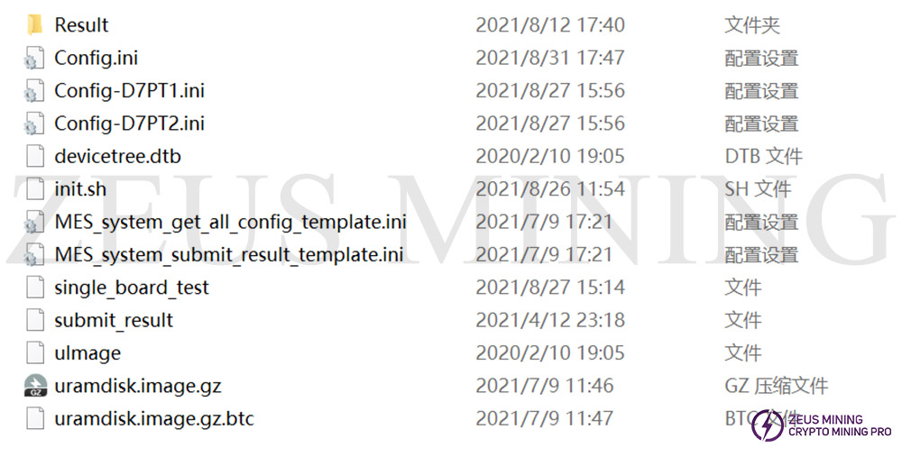
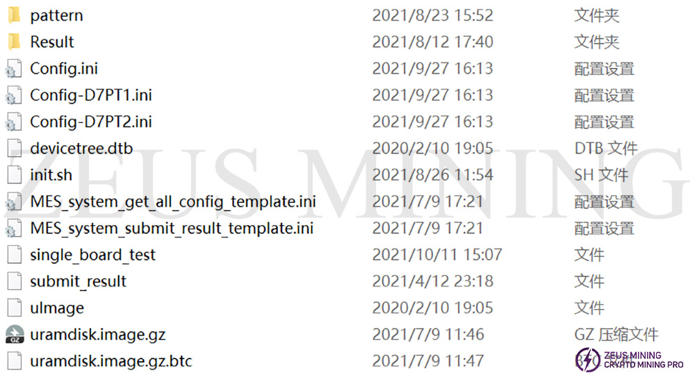
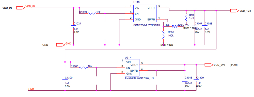
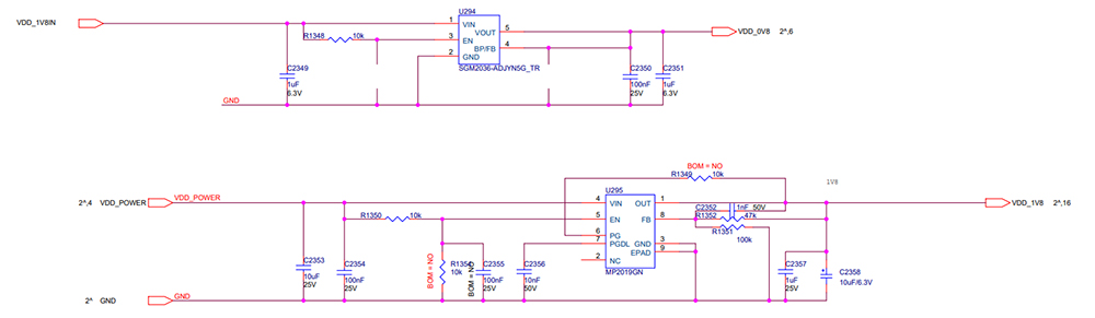
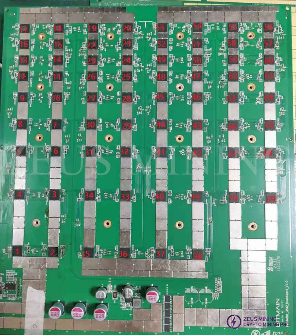
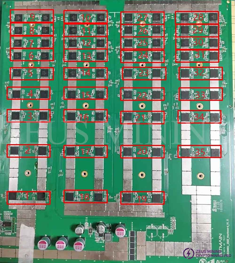
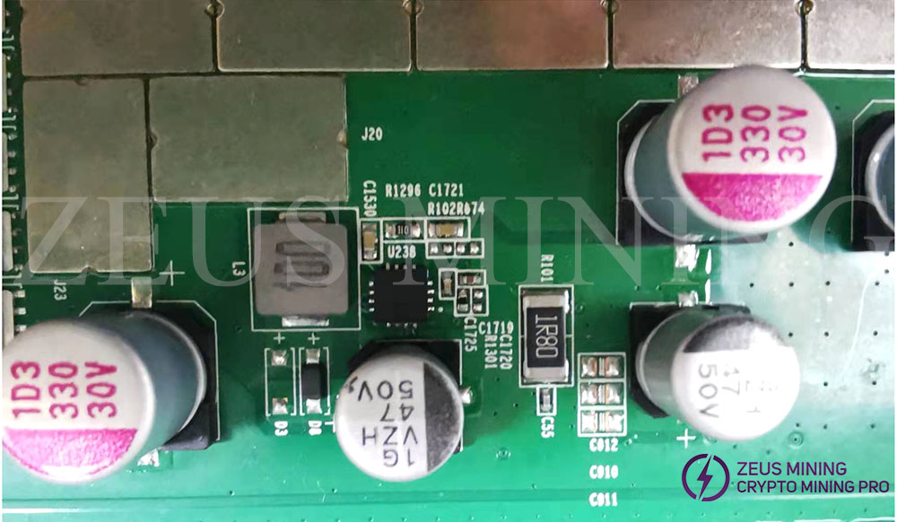
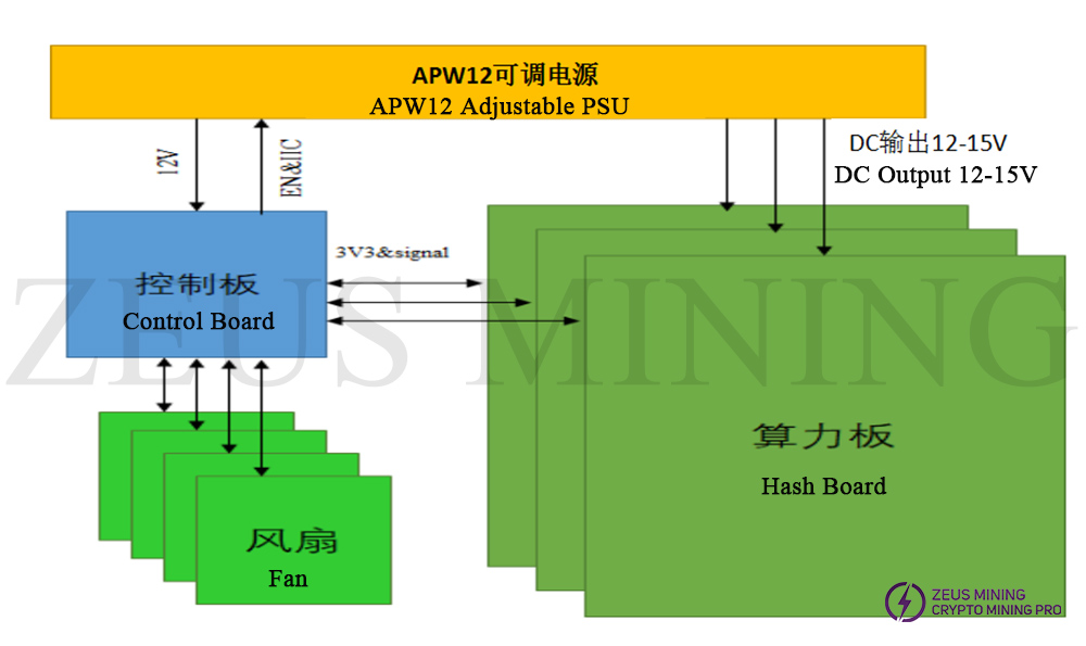
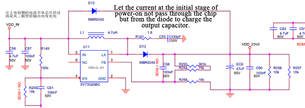
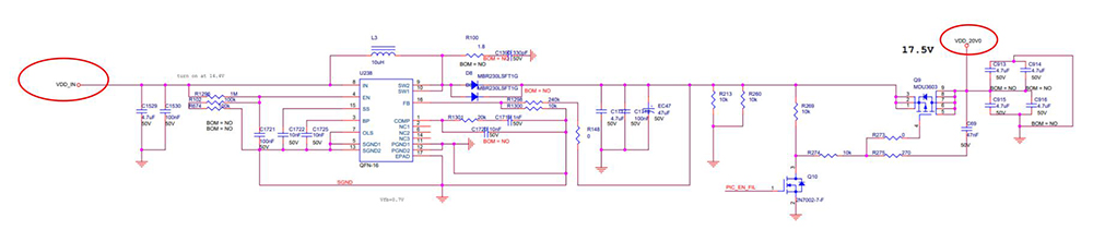
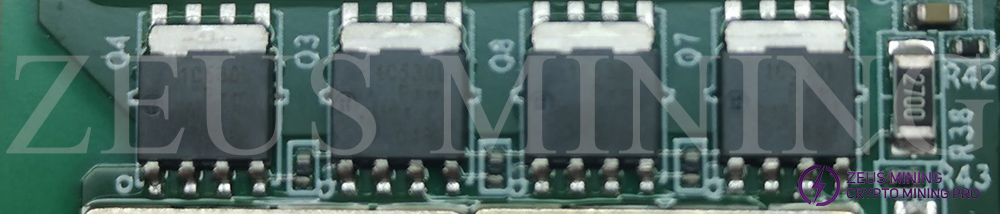
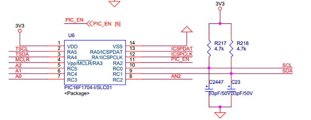
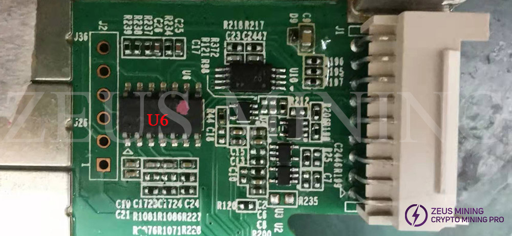
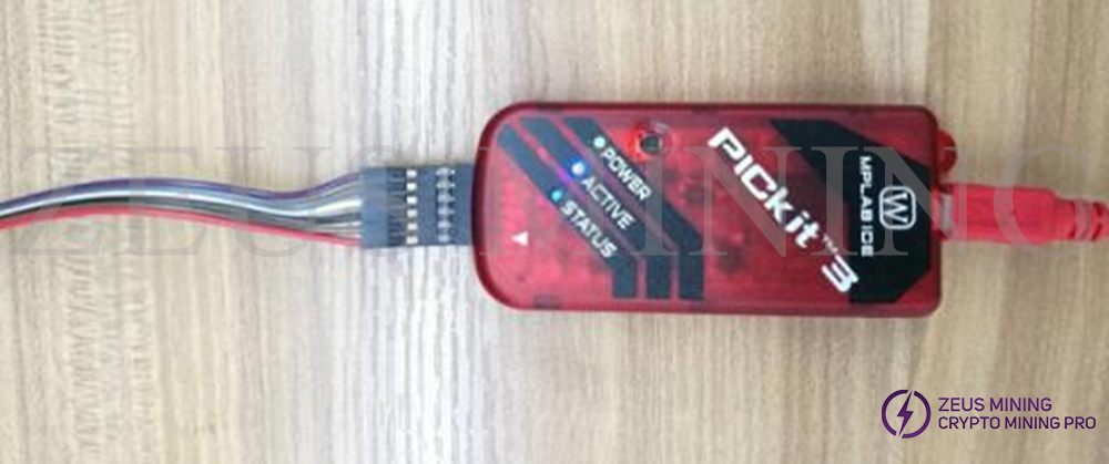
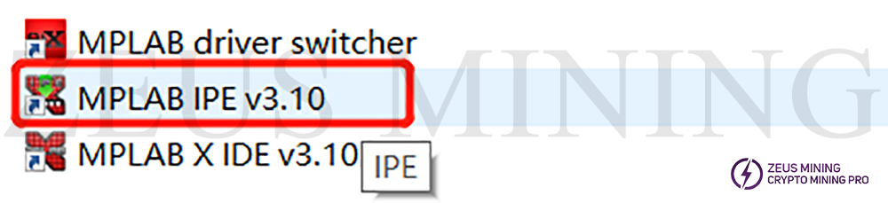
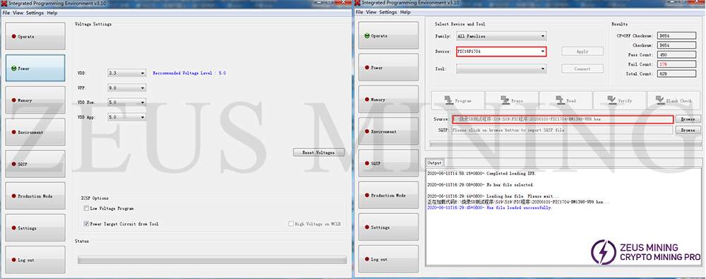
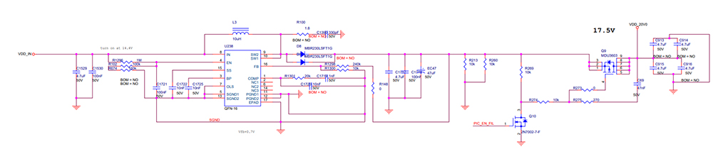
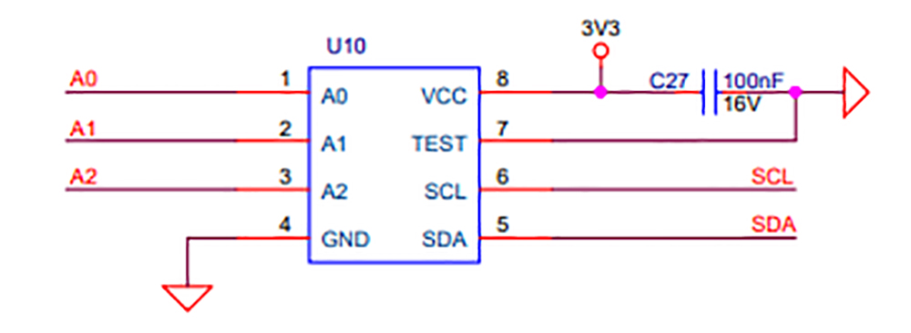
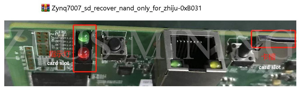
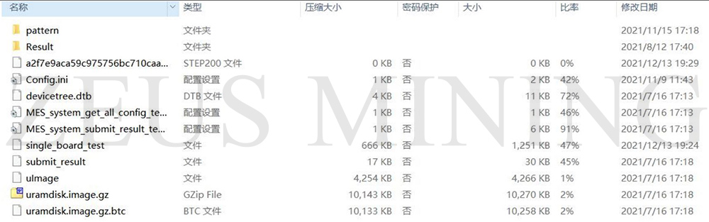
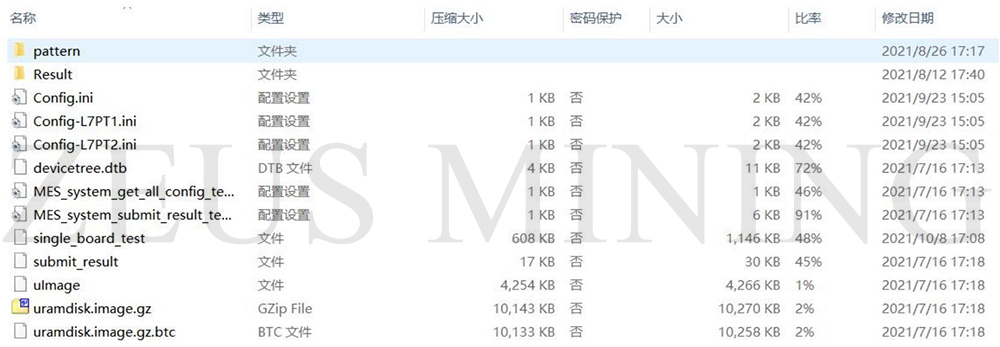
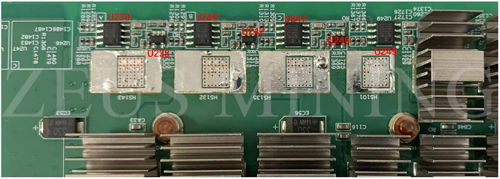
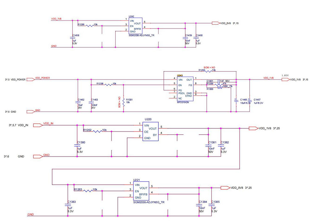
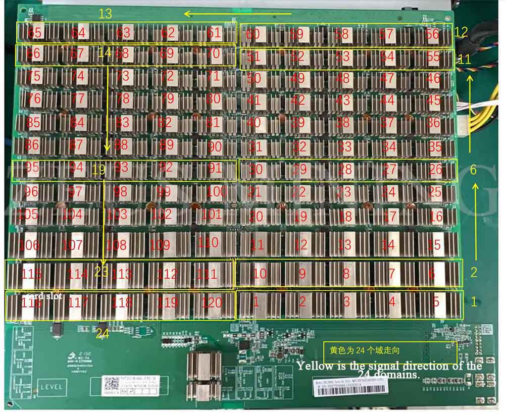
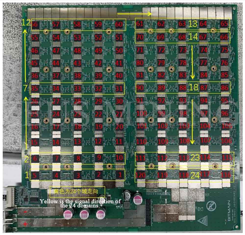
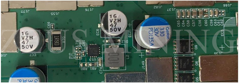
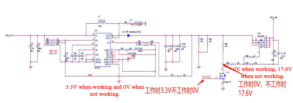
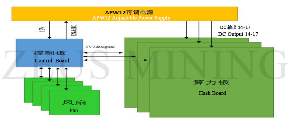
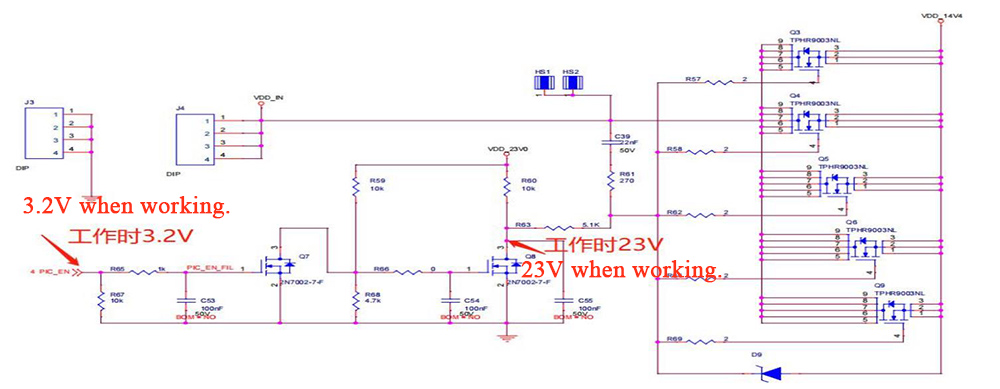
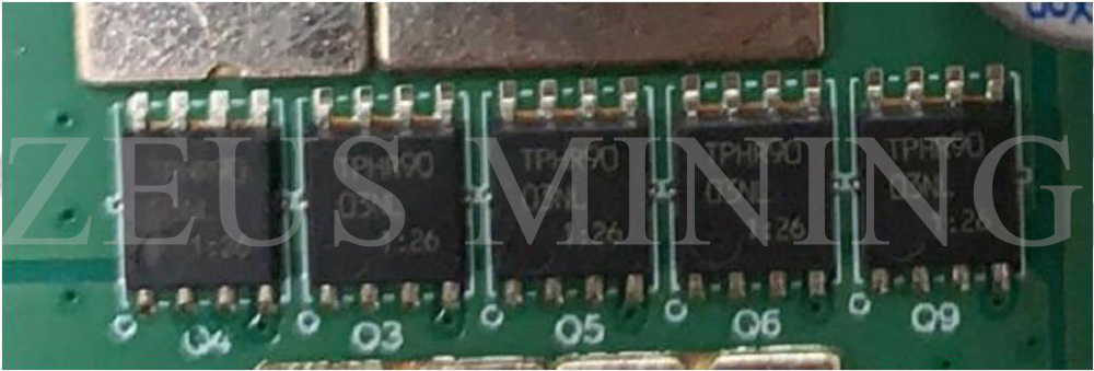
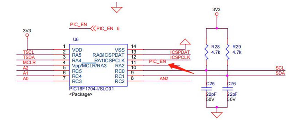
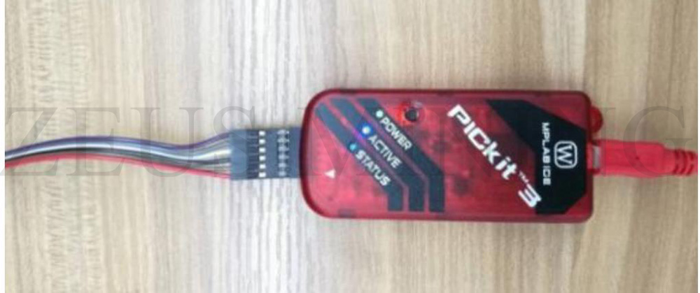
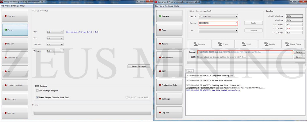
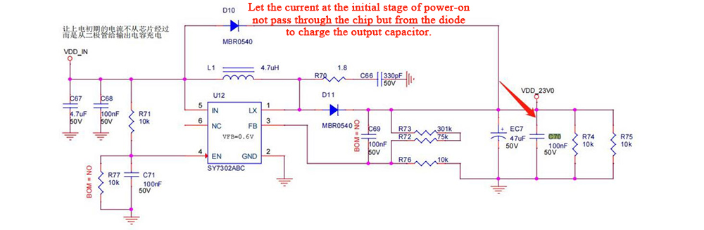
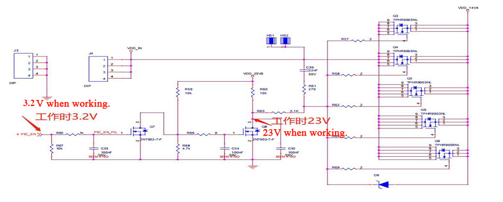
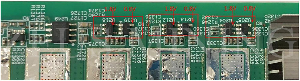
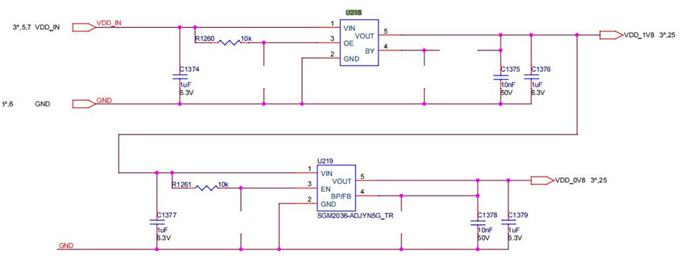
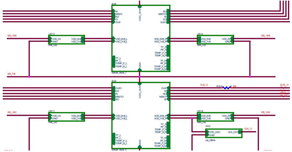
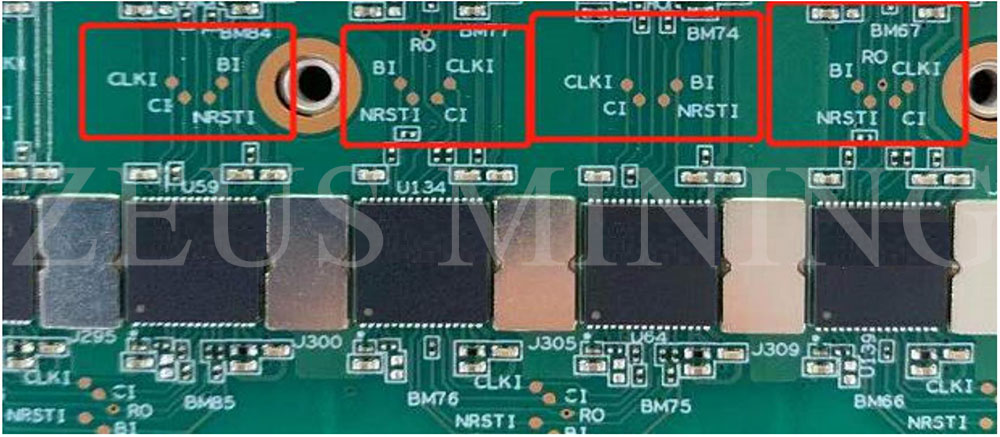
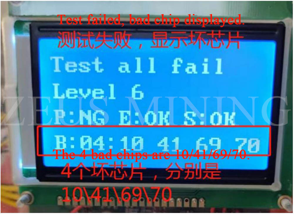
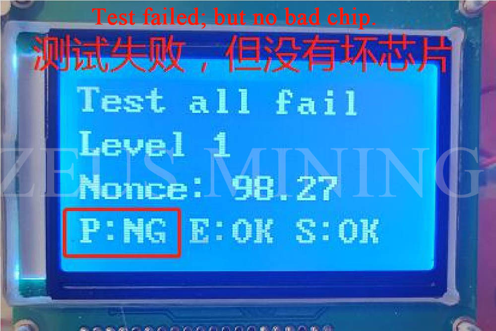
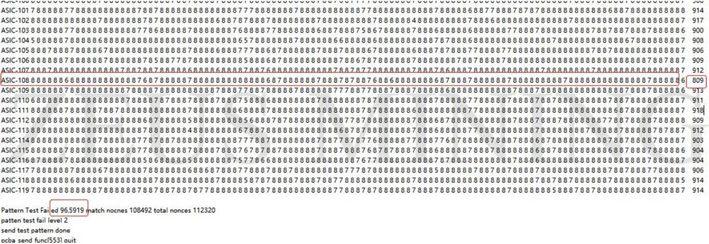
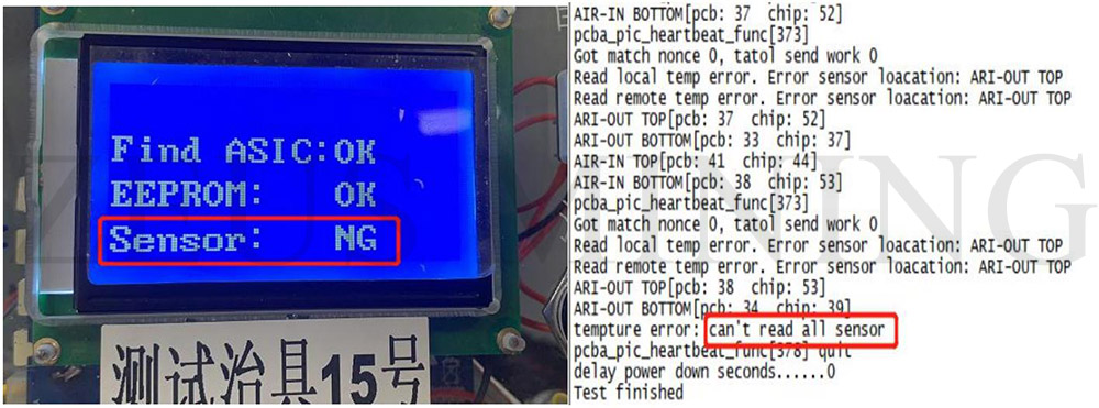
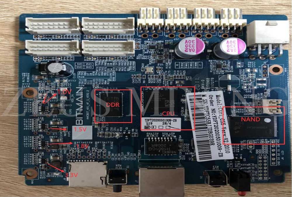
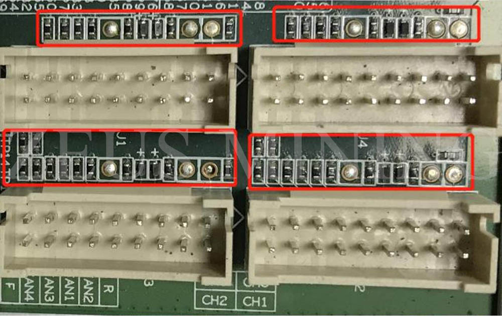
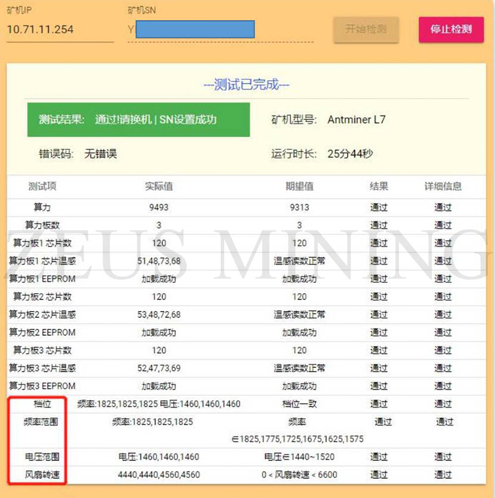
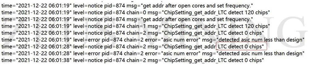
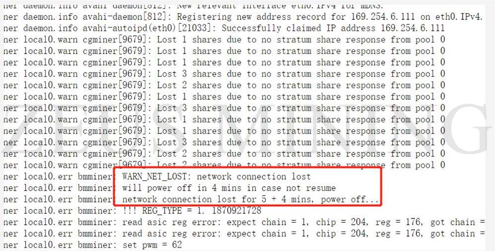
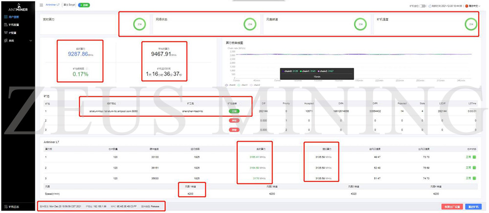
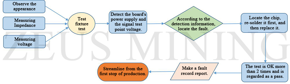
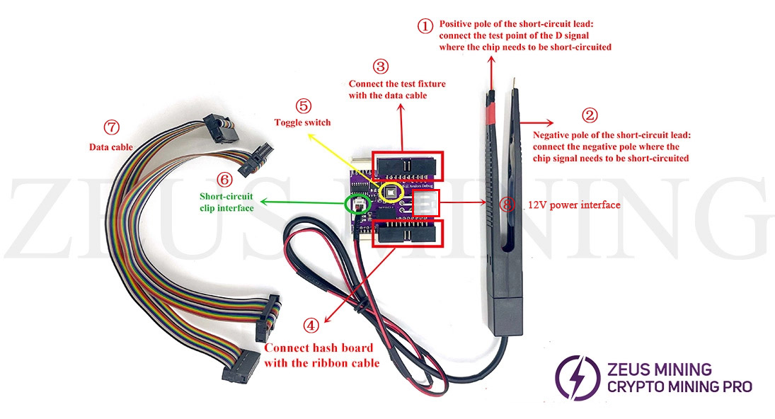
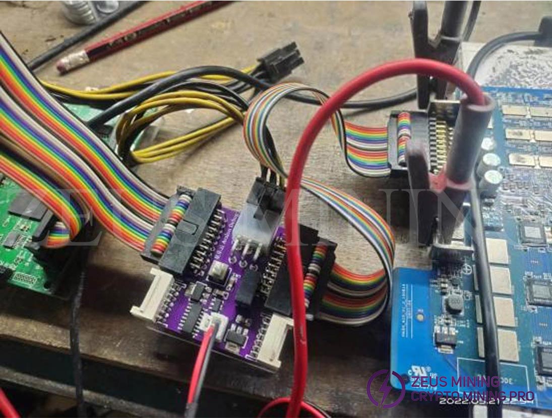
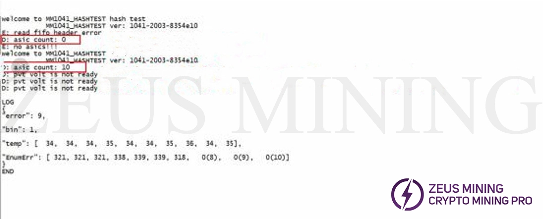
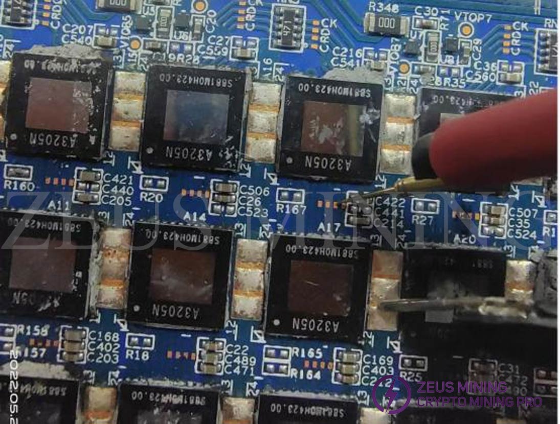
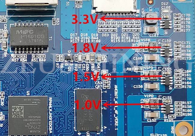
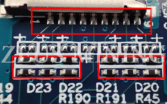
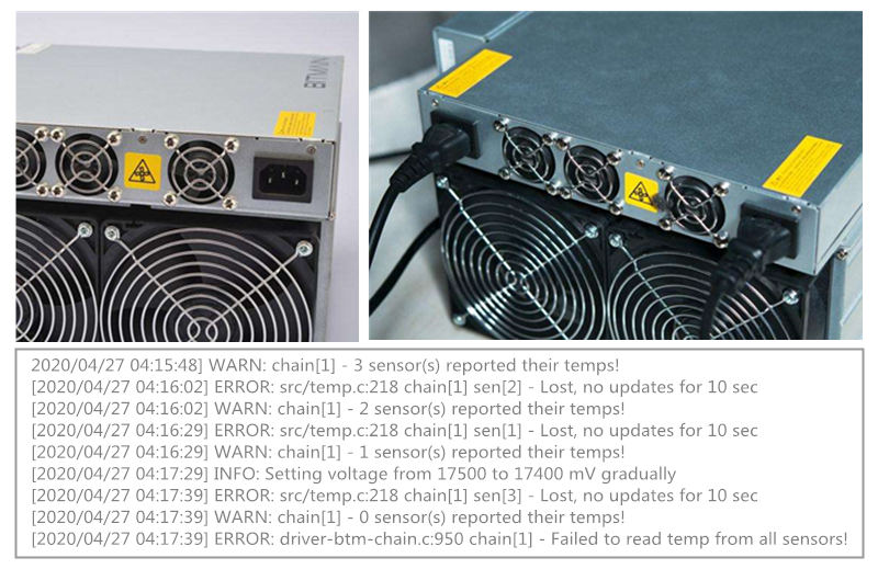
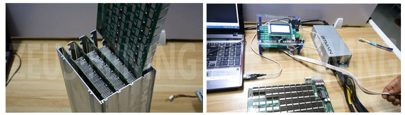
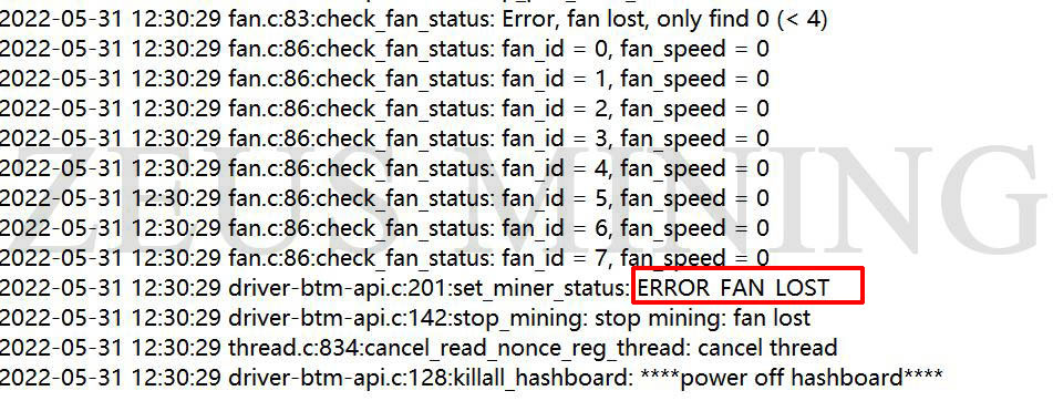
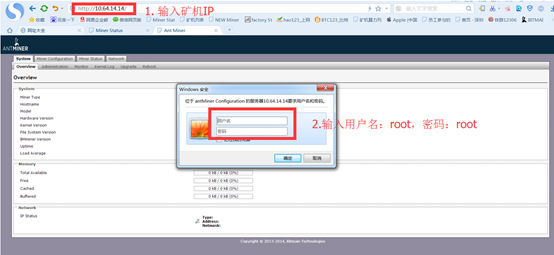
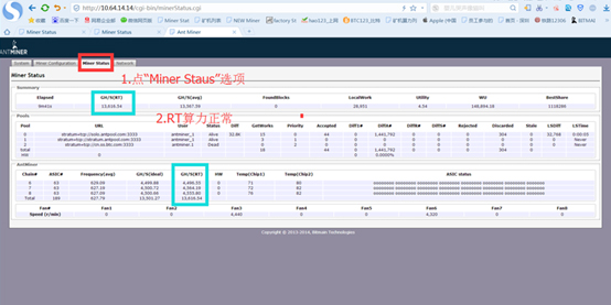
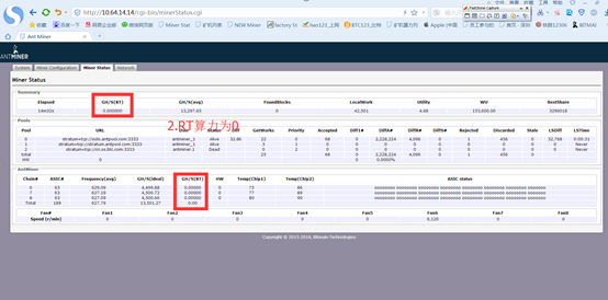
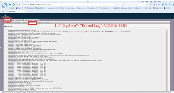
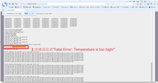
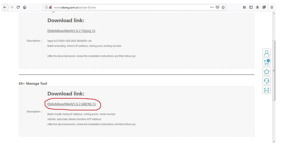
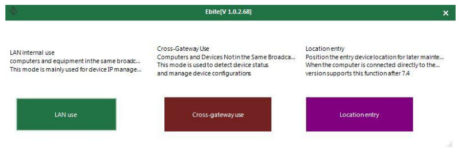
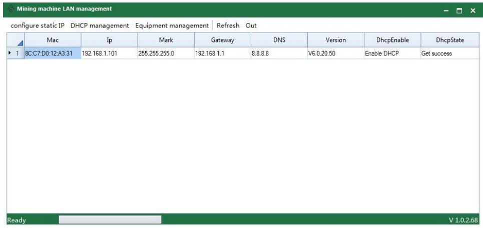
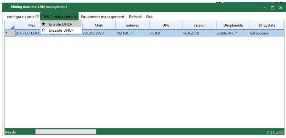
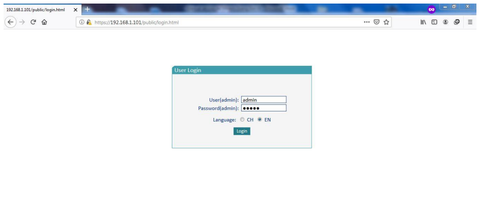
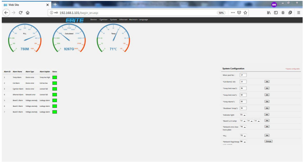
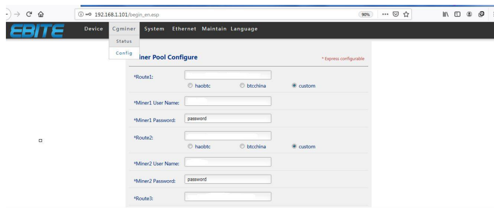
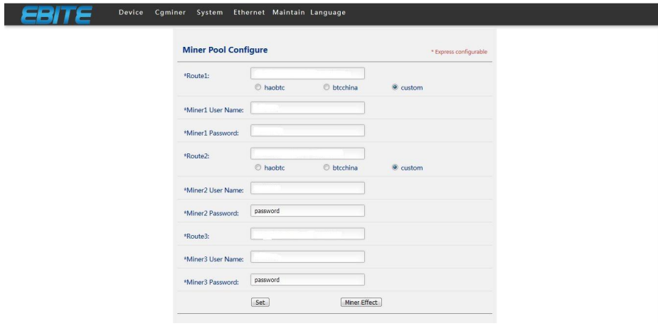
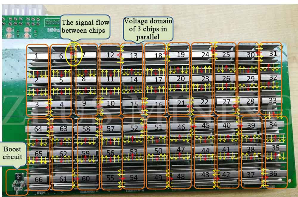
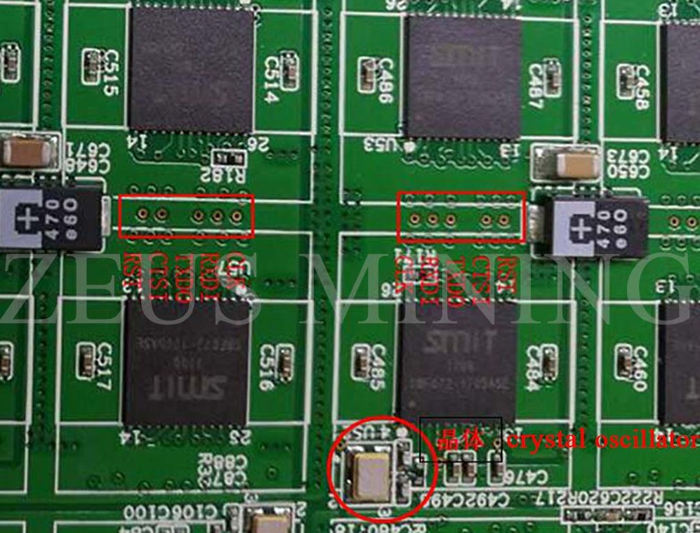
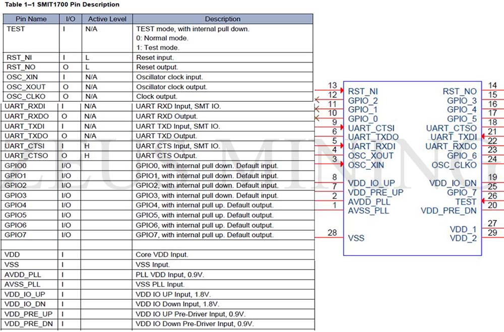
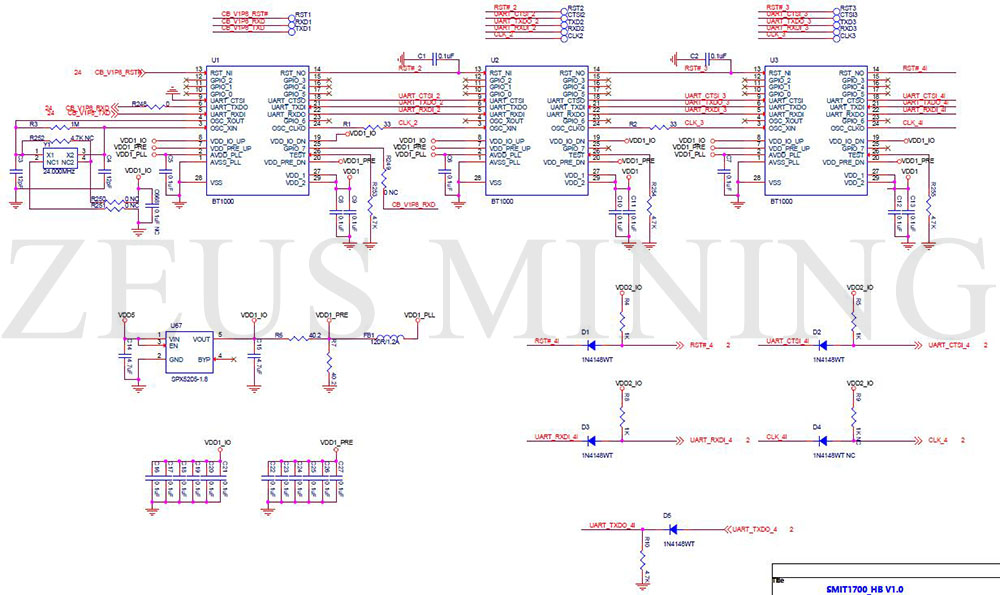
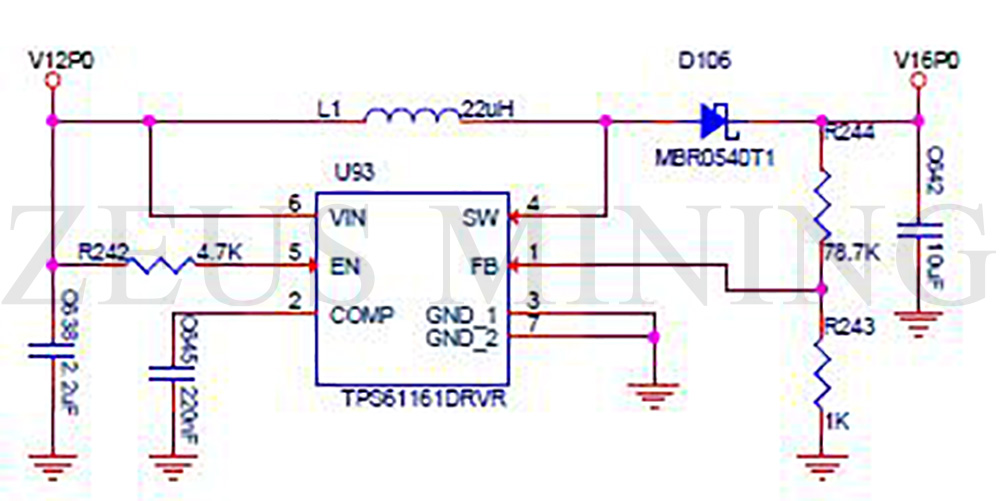
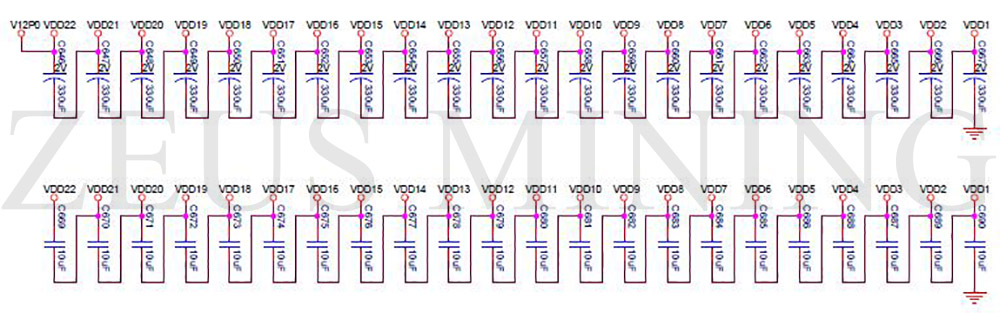
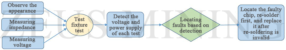
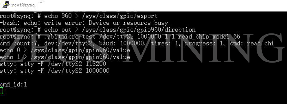
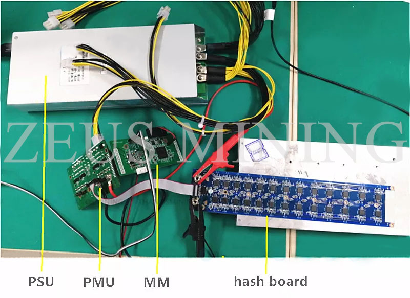
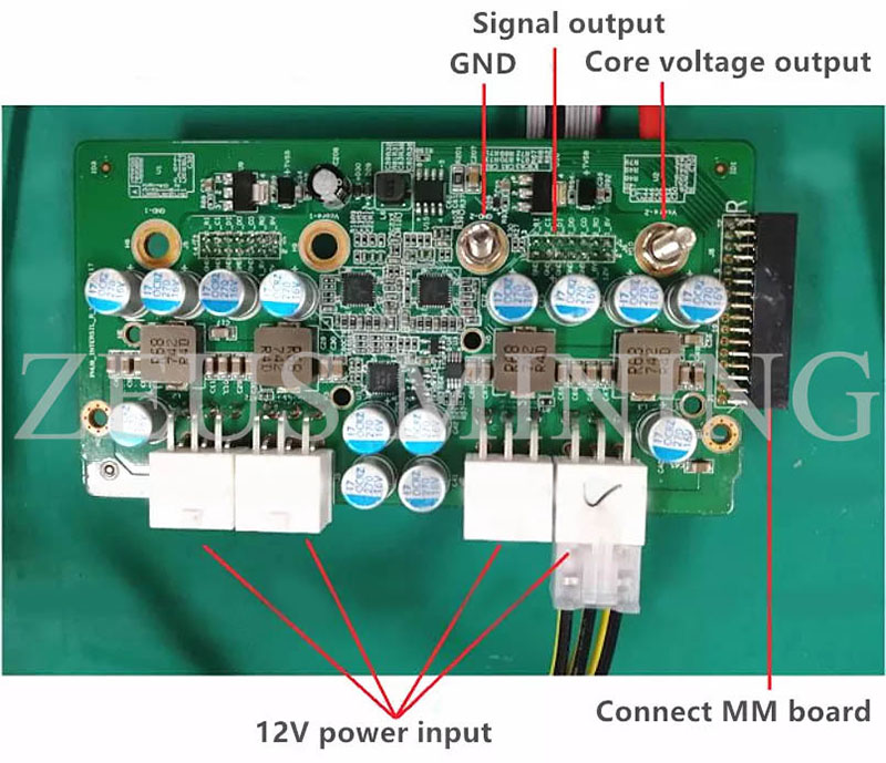
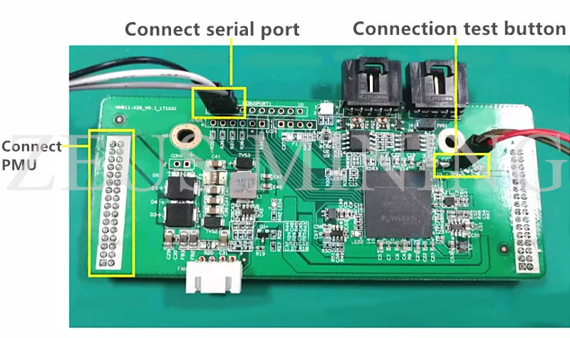
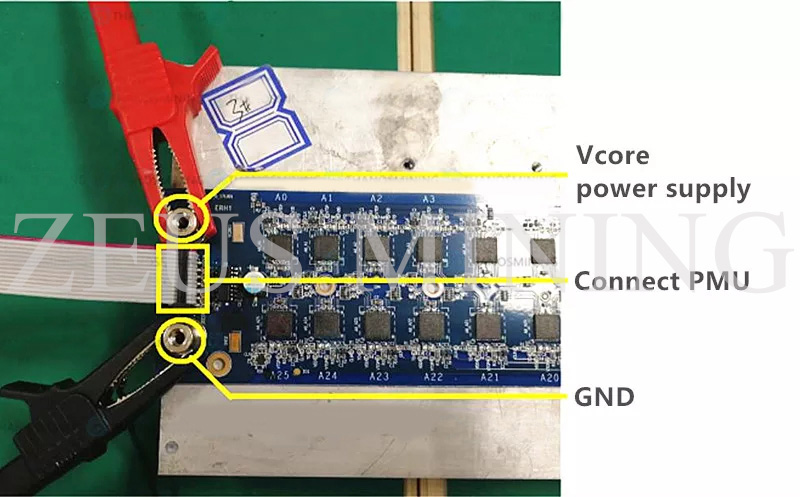
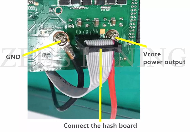
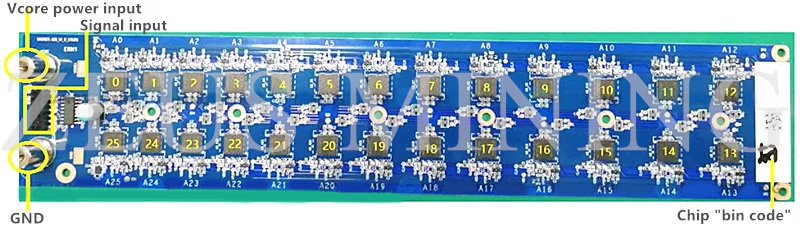
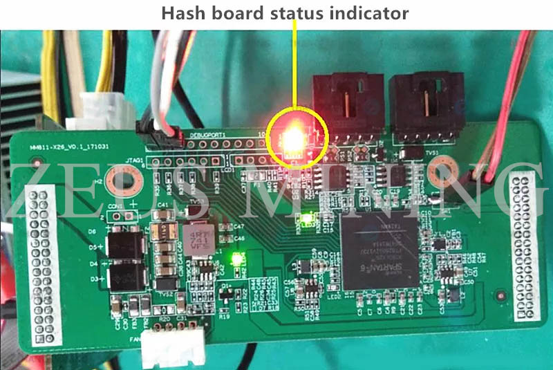
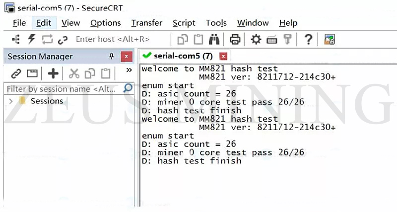
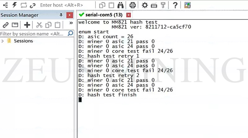
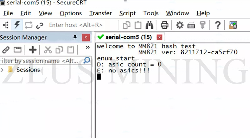
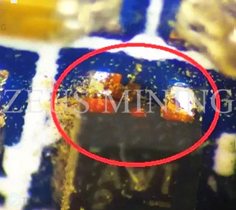
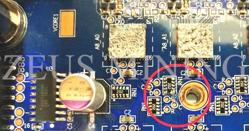
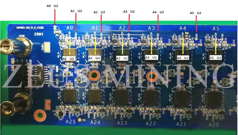
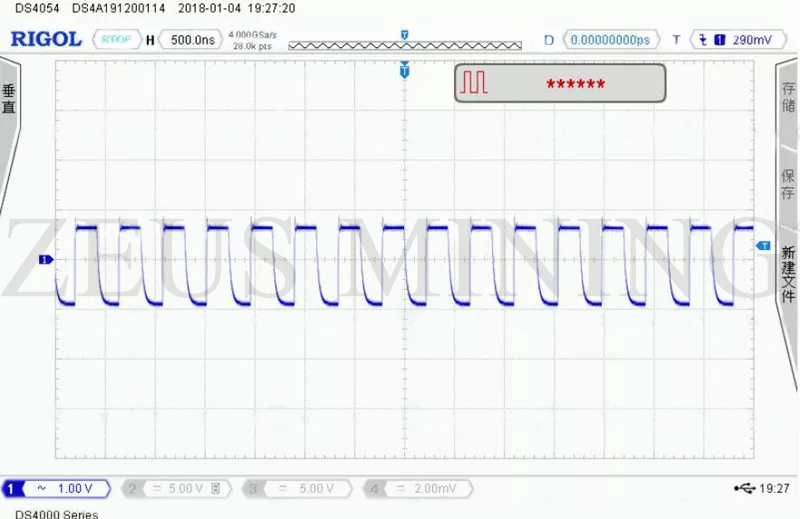