|
|
|
|
|
The trust scores you see are subjective; they will change depending on who you have in your trust list. |
|
|
Advertised sites are not endorsed by the Bitcoin Forum. They may be unsafe, untrustworthy, or illegal in your jurisdiction.
|
|
jstew
|
 |
January 17, 2017, 09:29:16 PM |
|
well my turn pots should be here tommorow or friday ill let u guys know how it goes since i have 6 boards to do.
one thing im usure about is what 2 points do i use to measure voltage with.
|
|
|
|
|
|
isoneguy
|
|
January 19, 2017, 01:29:53 PM |
|
I've a "dead" s7(700m 45chip) board I'd let go at slightly over shipping cost to one of you repair folks
|
|
|
|
|
|
jstew
|
|
January 19, 2017, 07:18:36 PM |
|
I've a "dead" s7(700m 45chip) board I'd let go at slightly over shipping cost to one of you repair folks
ill take it if it works on the boards i already have , my turnpots should be here tommorow edit just checked tracking and they will be here tomorrow so ill let u know |
|
|
|
|
|
jstew
|
|
January 23, 2017, 10:30:23 PM
Last edit: July 31, 2018, 11:31:06 PM by frodocooper |
|
first test board  think i soldered the red wire to the wrong leg though , find out in a few mins and holy crap this is hard to solder |
|
|
|
|
sidehack
Legendary

 Offline Offline
Activity: 3318
Merit: 1848
Curmudgeonly hardware guy

|
|
January 23, 2017, 10:37:51 PM |
|
That's why I'd just use hot air to replace the PIC. Less likely to hit the wrong thing. Course it also requires more complex tools.
|
|
|
|
|
jstew
|
|
January 23, 2017, 10:41:58 PM
Last edit: July 31, 2018, 11:29:45 PM by frodocooper |
|
That's why I'd just use hot air to replace the PIC. Less likely to hit the wrong thing. Course it also requires more complex tools.
i wish i had a hotair station, if this doesnt work i may just send theese boards off to you |
|
|
|
|
|
jstew
|
|
January 23, 2017, 10:48:27 PM
Last edit: July 31, 2018, 11:30:17 PM by frodocooper |
|
no luck on first board , i think i soldered to the wrong pins on the turnpot , redwire should be on the pin i cut off i believe, so ill try one more board. unfortunatly i left my multimeter at the shop so i cant even check it that way atm , ill have to grab it later  tried ever freq from 500 down to 100 in 100 increments miner always shows the oard as having 48 asics , none of the heatsinks are warming up either |
|
|
|
|
|
jstew
|
|
January 23, 2017, 11:45:21 PM
Last edit: July 31, 2018, 11:30:47 PM by frodocooper |
|
retried on another board and this one apears to be working  |
|
|
|
|
|
jstew
|
|
January 24, 2017, 12:05:35 AM
Last edit: July 31, 2018, 11:31:37 PM by frodocooper |
|
second board is fixed , i have it running at 500 freq/1.2 th , dont have my volt meter to set the voltage to run it at 700, so ill take care of that later tonight. this isnt an easy fix by any means soldering to r17 is a royal pain , c76 isnt to bad but id imagine u could just solder to gnd on the pcie plug instead of the side of c76. that would make it a lil easier that being said im sending the remainder of my boards to sidehack for pic replacement , instead of soldering the rest myself  |
|
|
|
|
NotFuzzyWarm
Legendary
 Online Online
Activity: 3626
Merit: 2535
Evil beware: We have waffles!
|
|
January 24, 2017, 12:17:29 AM |
|
Glad to see it worked  re: this isnt an easy fix by any means soldering to r17 is a royal pain , c76 isnt to bad but id imagine u could just solder to gnd on the pcie plug instead of the side of c76. that would make it a lil easier Yessss it might/probably would work but -- when it comes to voltage regulators it is always best to keep the various returns as close to the regulator chip as possible. Really, that applies to all signal paths in any circuit... Minimizes phantom parasitic components. |
|
|
|
|
jstew
|
|
January 24, 2017, 12:30:46 AM |
|
Glad to see it worked re: this isnt an easy fix by any means soldering to r17 is a royal pain , c76 isnt to bad but id imagine u could just solder to gnd on the pcie plug instead of the side of c76. that would make it a lil easier Yessss it might/probably would work but -- when it comes to voltage regulators it is always best to keep the various returns as close to the regulator chip as possible. Really, that applies to all signal paths in any circuit... Minimizes phantom parasitic components. thanks if i do do anymore maybe ill just keep ground at c76 then , its actually easier to solder then r17 |
|
|
|
|
|
bilabonic
|
|
February 04, 2017, 08:10:21 PM
Last edit: July 31, 2018, 11:32:29 PM by frodocooper |
|
Can ANYONE confirm what this 'fixes' ? I have an S7 with all '0's BUT Chain 3 only shows 30 asics#, average speed is 3000Gh !!!! 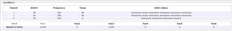 Cheers guys. |
BTC - 1Ayax24aAU8c1xwAakK94DVDkm4kbfZ8Ch
|
|
|
jamesb777
Jr. Member
 Offline
Activity: 49
Merit: 3
|
|
February 05, 2017, 07:05:48 AM
Last edit: July 31, 2018, 11:32:10 PM by frodocooper |
|
The PIC (programmable interface controller) is a chip that's used to communicate and control voltage with the ASIC chips. Basically it's there to make sure the ASIC chips are operating at the proper voltages and for temperature monitoring. I'm guessing this mod is used to bypass the PIC's controlling of voltage. In the case of your missing ASICs, from Bitmain's FAQ, they call it 'chip scission'. I believe there is an issue with the hardware around one of your ASIC chips causing the chain to be broken, I don't think this mod would be applicable in your case. Can ANYONE confirm what this 'fixes' ?
I have an S7 with all '0's BUT Chain 3 only shows 30 asics#, average speed is 3000Gh !!!!
[...]
Cheers guys.
|
|
|
|
|
|
bilabonic
|
|
February 05, 2017, 12:34:01 PM
Last edit: July 31, 2018, 11:32:51 PM by frodocooper |
|
The PIC (programmable interface controller) is a chip that's used to communicate and control voltage with the ASIC chips. Basically it's there to make sure the ASIC chips are operating at the proper voltages and for temperature monitoring. I'm guessing this mod is used to bypass the PIC's controlling of voltage.
In the case of your missing ASICs, from Bitmain's FAQ, they call it 'chip scission'. I believe there is an issue with the hardware around one of your ASIC chips causing the chain to be broken, I don't think this mod would be applicable in your case.
Thanks for the reply James, idid read through the thread an understood it 'bypassed' the voltage control os the asic chips in paralleled.. I think an option for me would be to 'clean' the boards and see what reults i get. Cheers |
BTC - 1Ayax24aAU8c1xwAakK94DVDkm4kbfZ8Ch
|
|
|
LBNG
Newbie
Offline
Activity: 1
Merit: 0
|
|
February 10, 2017, 03:33:22 AM |
|
In all the pictures shown in this thread the U2 chip remains in place. It is just that they removed it after taking the picture? Just want to confirm that I need to remove it for this fix to work.
|
|
|
|
|
|
icside
|
|
March 15, 2017, 05:53:39 PM |
|
just did this mod to fix like 3/4 of my S7's. it worked on probably 5/6 of my dead boards. nobody at bitmain or any other mining company was willing to provide this info, and it's strikingly, frustratingly simple. many, many thanks to everybody here for saving me some time and money.
if i were to provide any input, i'd suggest not using a pot but a fixed value resistor as that connection is a current-sense circuit which is probably somewhat noise sensitive. at least use the most compact potentiometer with the shortest leads that you can.
anybody know any of the other common fixes they have in their list? curious if I can try fixing the last few dead boards I have, or if the next most common fix is resoldering ASICs...
|
|
|
|
Dibblah
Newbie
Offline
Activity: 56
Merit: 0
|
|
March 15, 2017, 10:30:55 PM |
|
As far as I can see, the ONLY fix they do really is resoldering ASICs. On the S7, it's not much fun, either.
I've been fiddling about a bit with the VRM and stuff on the board. The LM27402 is a quite nice chip, goes all the way down to .6v output - and the WebBench tools are absolutely awesome. So, theoretically, if the top side of the board has too many faulty ASICs, you could jumper the heatsinks to "cut them out" of the chain.
The only problems I am having are ringing (obviously, a proper poured power plane looks nothing like a relatively thin bridge electrically) and that damn clock snaking over the board. I am unsure of how possible it is to disconnect the clock chain and add back in the oscillator modules that haven't been stuffed.
Also looking with envious eyes at the NEC Tokin caps as used in the PS3 - insanely low ESR.
There's a couple of lessons I learned playing around, though. Firstly, cheap pots are cheap and very occasionally will run over a grain of dirt. When they do this, they go from ~1.5k in a fraction of a second to infinite resistance. Since these SMPSUs are designed to be insanely good at levelling out droops caused by high current draws, the power supply then sees that it's outputting essentially 0v. And ramps the output up to 12v. That leads onto the second thing I learned. It's amazing how much smoke a tiny little chip can emit when you put 12v @ 120A (instantaneous) or so through it.
|
|
|
|
|
|
icside
|
|
March 15, 2017, 10:46:11 PM |
|
There's a couple of lessons I learned playing around, though. Firstly, cheap pots are cheap and very occasionally will run over a grain of dirt. When they do this, they go from ~1.5k in a fraction of a second to infinite resistance. Since these SMPSUs are designed to be insanely good at levelling out droops caused by high current draws, the power supply then sees that it's outputting essentially 0v. And ramps the output up to 12v. That leads onto the second thing I learned. It's amazing how much smoke a tiny little chip can emit when you put 12v @ 120A (instantaneous) or so through it.
HAH! Yeah, one of the more fun stories I've been told is about a slow but unstoppable fire created by a low-voltage short on a PCB connected to a ~500A 5V power supply. the board caught on fire, and the power supply gave zero fcks. just kept sourcing more and more current, fire got bigger, etc. Re: re-soldering the ASICs: I've hand-re-flowed 1mm pitch BGA FPGAs and know the pains (especially with the temperatures required for lead-free solder and the temperatures most low-quality FR4 delaminates / melts / catches on fire). I think that Bitmain has always been smart enough to use DFN's with a ground/thermal slug IIRC? DFNs I've found to be difficult but much easier in comparison for rework. The problem is I have no idea how to figure out which are dead and which are alive.... |
|
|
|
Dibblah
Newbie
Offline
Activity: 56
Merit: 0
|
|
March 15, 2017, 11:08:17 PM |
|
Unfortunately, the bm1385 is 0.4mm pitch QFNish - with an exposed pad used as ground. So it's a bit of a nightmare to solder. Also if you have a newer board, it'll come with wonderful black adhesive holding the heatsinks onto the board. Not onto the chips, the board - they've used so much adhesive that it has squished out and forms a sort of poor-man's infill around the chip.
|
|
|
|
|
|


